5.If more adjustment is needed, the adjustment screws can be completely removed, and the bracket set to a NEW
6.Zip center panel of back cover closed.
ADJUSTING THE ULTI-MATE BASE DEPTH.
1.If necessary, unzip center panel of the back cover.
2.Loosen the four (4) mounting screws that secure the growth bracket to the
3.Adjust the seat forward or back until the desired mounting position is obtained.
4.Securely tighten the two (2) mounting screws.
5.If more adjustment is needed, the adjustment screws can be completely removed, and the bracket set to a NEW
6.Zip center panel of back cover closed.
Top Mounting
Screws
Bottom Mounting
![]() Screws
Screws
FIGURE 3 - ATTACHING / ADJUSTING THE
ADJUSTABLE ANGLE GROWTH
BRACKET
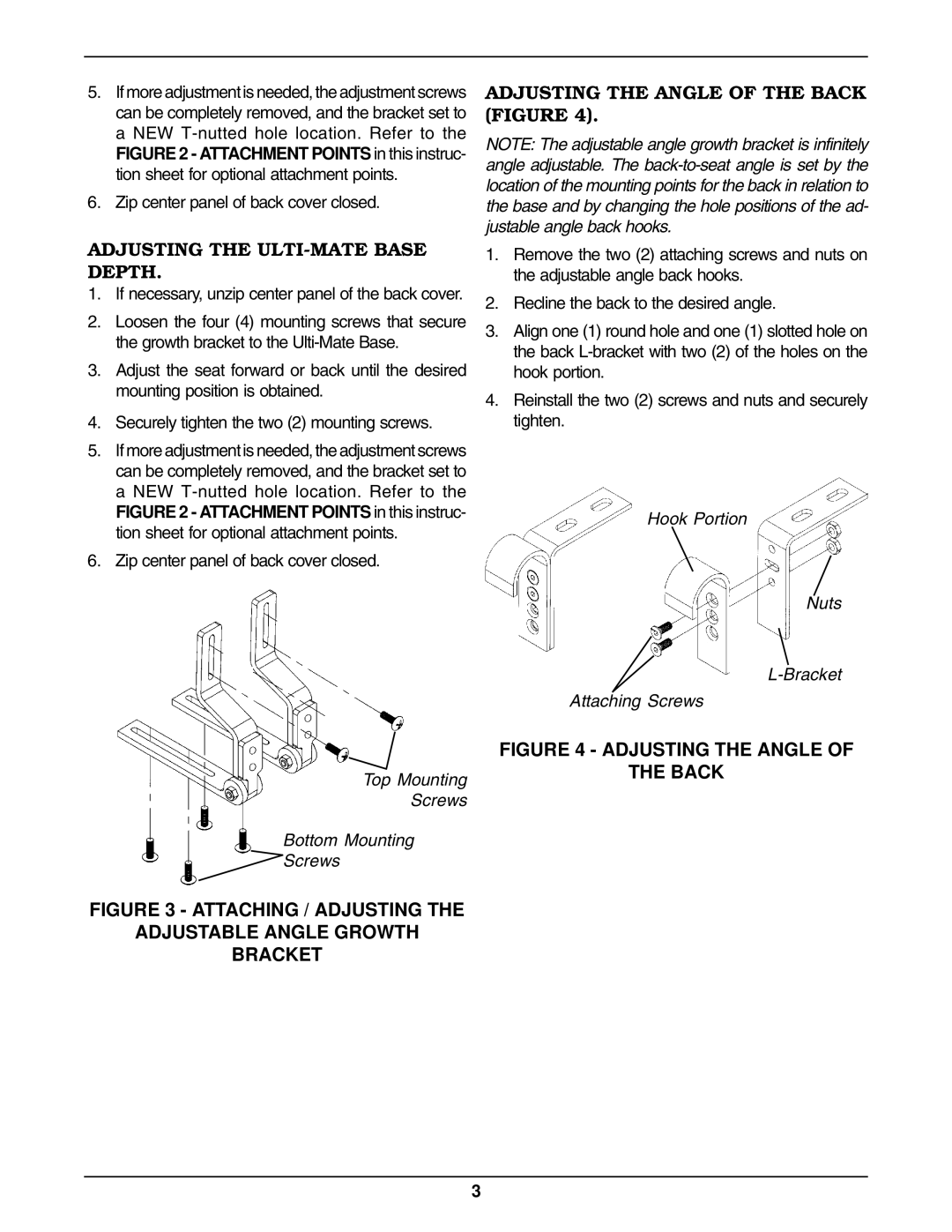
ADJUSTING THE ANGLE OF THE BACK (FIGURE 4).
NOTE: The adjustable angle growth bracket is infinitely angle adjustable. The
1.Remove the two (2) attaching screws and nuts on the adjustable angle back hooks.
2.Recline the back to the desired angle.
3.Align one (1) round hole and one (1) slotted hole on the back
4.Reinstall the two (2) screws and nuts and securely tighten.
Hook Portion
Nuts
Attaching Screws
FIGURE 4 - ADJUSTING THE ANGLE OF
THE BACK
3