Tray Mounting Hardware
Assembly, Installation and Operating Instructions
Right Side Hardware | Left Side Hardware |
Part Nos.TR40R | Part No.TR40L |
|
|
SAVE THESE INSTRUCTIONS
NOTE: Check all parts for shipping damage before using. In case of damage, do not use. Contact the dealer for fur- ther instructions.
SAFETY SUMMARY
The following reccommendations are made for safe in- stallation and use of the Tray Mounting Hardware:
GENERAL WARNINGS
DO NOT install this equipment without first reading and understanding this instruction sheet. If you are unable to understand these Warnings, Cautions and Instructions, contact a healthcare professional, dealer or technical personnel if applicable be- fore attempting to install this equipment - otherwise, injury or damage may occur.
Consult a physician or therapist for ap- propriate positioning of the tray relative to the user.
Your therapist and physician should be con- sulted if you have any questions regard- ing individual limitations and needs.
The tray mounting hardware is available in two versions TR40R: Right side hardware (shown)
TR40L: Left side hardware
6.Insertthesupportarmfullyintothetrayreceptacle untilit cannot move further back.
7.Have the user sit in the wheelchair and position the tray on the armrests, evenly spaced on both sides.
8.Withapenlocateandmarkthefour(4)drillpointsonthe tray by using the support arm bracket as a template.
9.Using a 1/4" drillbit, drill four (4) holes corresponding to the marks made with the pen.
NOTE: This product is designed to work with Invacare trays LTACL, LTCCL, LTACCL and LTCCCL. The Invacare tray mounting hardware can also be installed on other manufac- turers' trays if the tray rim does not interfere with the opera- tion of the tray support arm.
CAUTION
DO NOT drill too deep as this will render the tray useless.
10.
11.Mountthetrayusing theflatscrews,washers,andacorn nuts with the hex key wrench provided. DO NOT over- tighten screws.
12.With the user sitting in the wheelchair, adjust the tray to the desired position and tighten knob on receptacle.
NOTE: The strap on the tray may be removed or wrapped around armrest for additional support.
Tools Required:
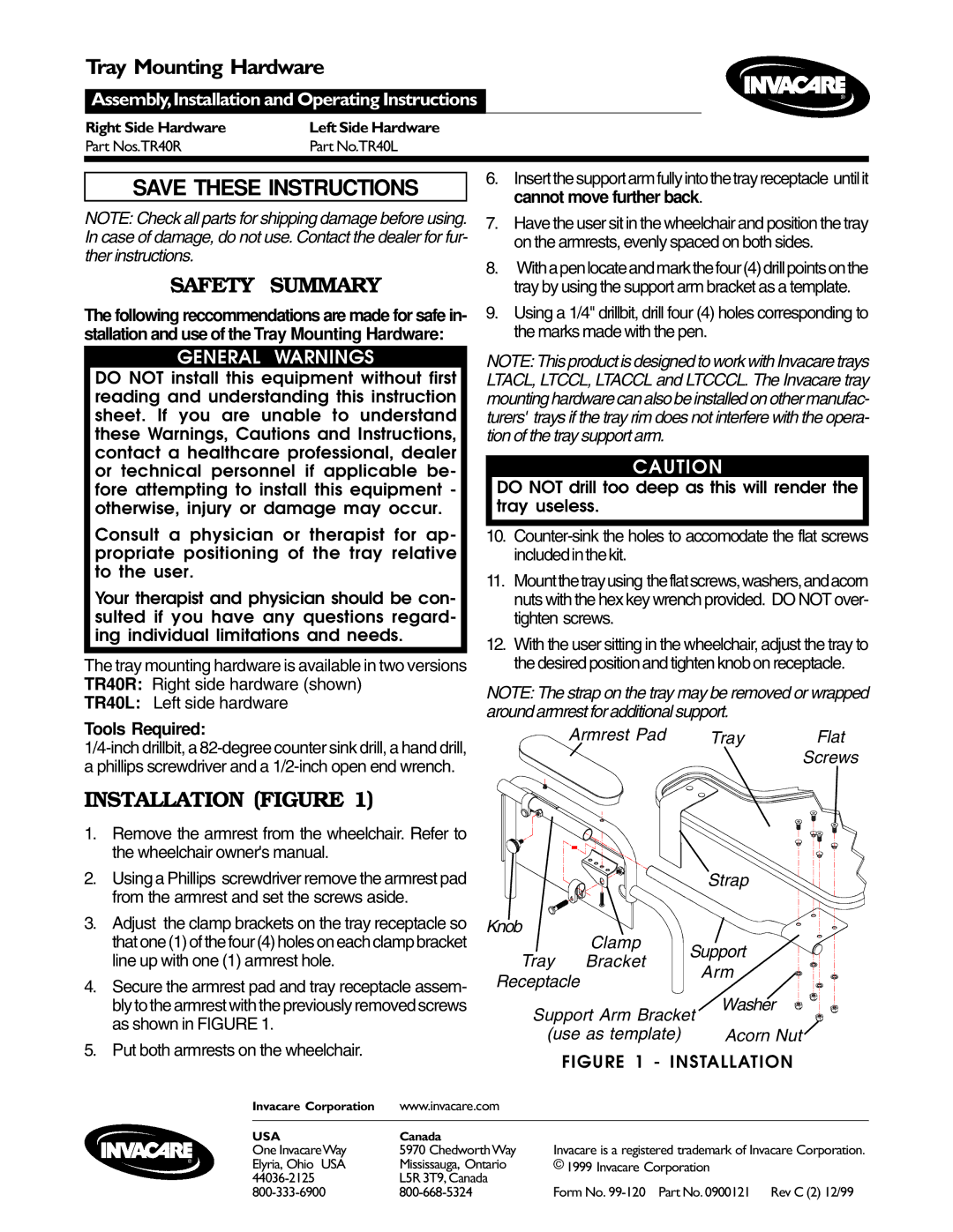
INSTALLATION (FIGURE 1)
1. | Remove the armrest from the wheelchair. Refer to |
| the wheelchair owner's manual. |
2. | Using a Phillips screwdriver remove the armrest pad |
| from the armrest and set the screws aside. |
3. | Adjust the clamp brackets on the tray receptacle so |
| that one (1) of the four (4) holes on each clamp bracket |
| line up with one (1) armrest hole. |
4. | Secure the armrest pad and tray receptacle assem- |
Armrest Pad
Knob
Clamp
Tray Bracket
Receptacle
Tray Flat Screws
Strap
Support
Arm
bly to the armrest with the previously removed screws |
as shown in FIGURE 1. |
5. Put both armrests on the wheelchair. |
Support Arm Bracket | Washer |
| |
(use as template) | Acorn Nut |
FIGURE 1 - INSTALLATION
Invacare Corporation | www.invacare.com |
|
|
USACanada
One InvacareWay Elyria, Ohio USA
5970 ChedworthWay Mississauga, Ontario L5R 3T9, Canada
Invacare is a registered trademark of Invacare Corporation. © 1999 Invacare Corporation
Form No.
