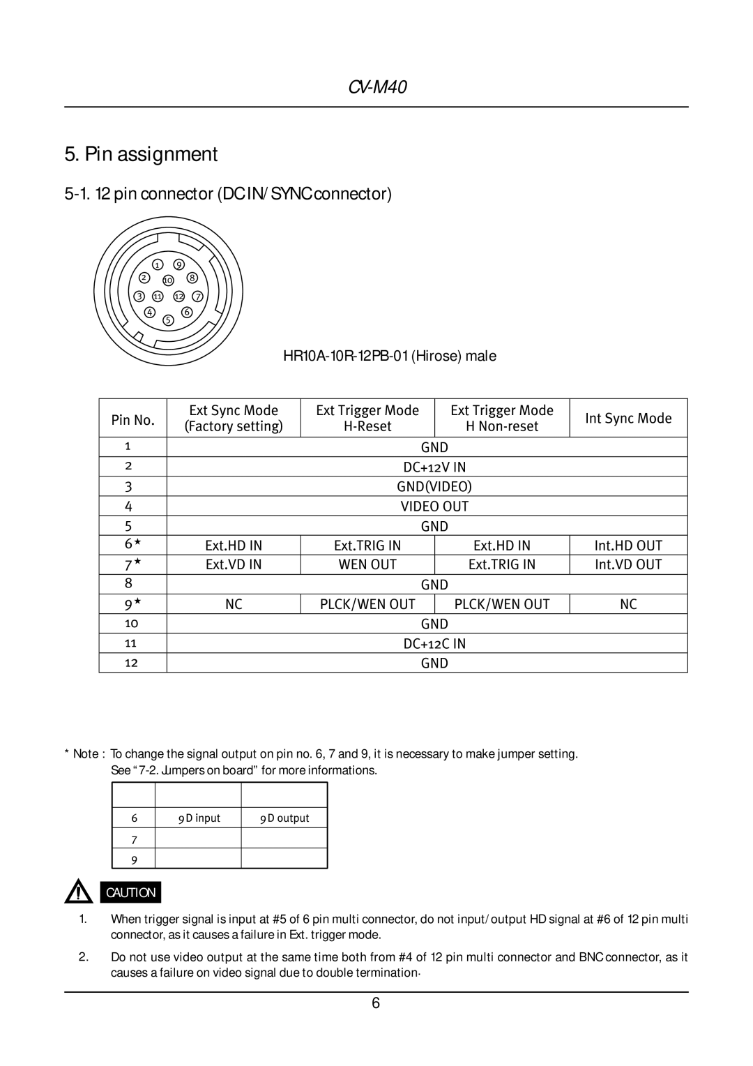
5. Pin assignment
5-1. 12 pin connector (DC IN/SYNC connector)
Pin1No. | ExtSyncMode | IntSyncMode | ||||||
(Factorysetting) |
|
|
| |||||
6 |
|
| GND(VIDEO) |
|
| |||
2 |
|
|
| DC+12VIN |
|
|
| |
3 |
|
|
|
|
|
|
|
|
4 |
|
|
|
| OUT |
|
| |
5 | Ext.HDVIN | Ext.TRIGIN |
| Ext.HDIN | Int.HDVOUT | |||
7 |
|
|
| |||||
OUT |
|
|
| Ext.TRIGIN | ||||
90 | NC | PLCK/WENOUT | PLCK/WENOUT | NC | ||||
8 |
|
|
| DC+12CGNDIN |
|
|
| |
12 |
|
|
|
|
|
| ||
1 |
|
|
|
|
|
|
|
|
*Note : To change the signal output on pin no. 6, 7 and 9, it is necessary to make jumper setting.
CAUTION
1.When trigger signal is input at #5 of 6 pin multi connector, do not input/output HD signal at #6 of 12 pin multi connector, as it causes a failure in Ext. trigger mode.
2.Do not use video output at the same time both from #4 of 12 pin multi connector and BNC connector, as it causes a failure on video signal due to double termination.
6
