CV-M530/531
Cautions in the Start/Stop Trigger Mode.
1. The input of ext. VD signal must be given continuously to synchronize with int. VD signal. It is not possible to input ext. VD signal randomly.
2. The exposure start may delay up to 1H max., when the falling edge of ext. trigger pulse is not synchronized with the falling edge of ext. HD signal. To avoid this 1H jitter and delay, the falling edge of the ext. trigger pulse should be synchronized within 4.4 µsec. to the HD pulse. It can be the ext. HD input or the internal HD output.
Shown under cautions in Edge
3. In this mode, the ext. trigger has to be TTL level (2.0 to 5.0 V). It cannot be 75 Ohm terminated. The duration should be more than 1 H negative going. >64 µsec. and < 1 msec. The input is AC coupled.
4. If the ext. VD input and ext. HD input are from a source with TTL level, set
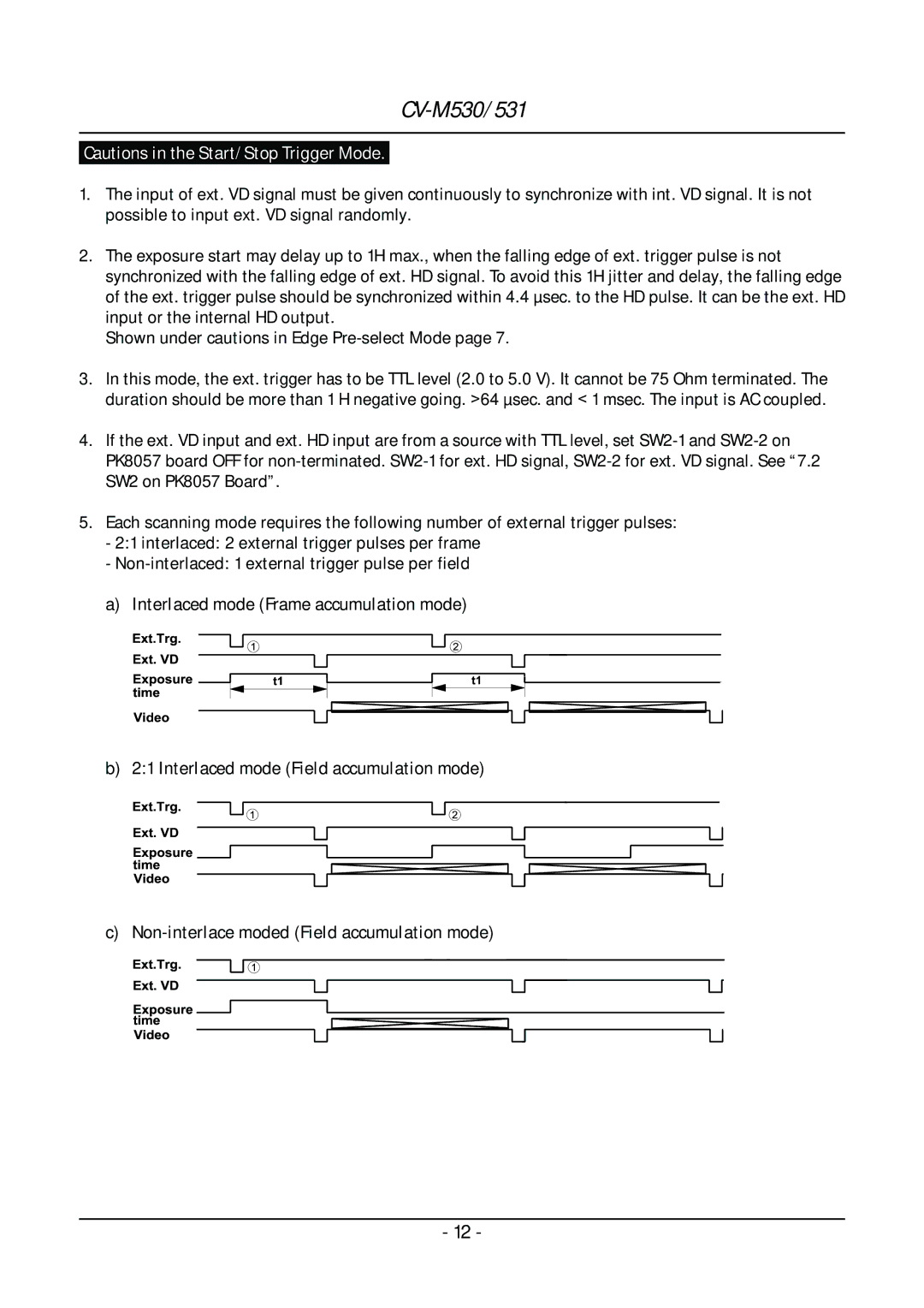
5. EachExscanningt.Trg. mode requires the following number of external trigger pulses: - 2:1 interlaced:VD 2 external trigger pulses per frame
-
b) 2:1ExtimeVideotposure.TrgInterlacedVD. mode1 (Field accumulation mode)2
c)
- 12 -