24C/CT specifications
The JBL 24C/CT is an advanced ceiling speaker designed to deliver exceptional sound quality while seamlessly integrating into a variety of environments. Specifically tailored for commercial applications, this speaker is an ideal choice for restaurants, offices, retail spaces, and more.One of the standout features of the JBL 24C/CT is its versatile design, which allows it to be easily installed in drop ceilings. With a 4-inch full-range driver, the speaker produces clear and detailed audio across a broad frequency spectrum. This makes it perfect for background music, announcements, and engaging presentations.
The JBL 24C/CT is built with the latest technologies to enhance its performance. Its advanced coaxial driver design features a low-distortion motor structure, ensuring clean and accurate sound reproduction. The speaker’s wide dispersion characteristics allow it to fill a room evenly, minimizing dead spots and ensuring every listener enjoys the same audio experience.
Another remarkable aspect of the JBL 24C/CT is its power handling capability. It can handle up to 15 watts of power, making it suitable for various amplification systems. Its low impedance design ensures compatibility with a wide range of amplifiers, providing flexibility for system integration.
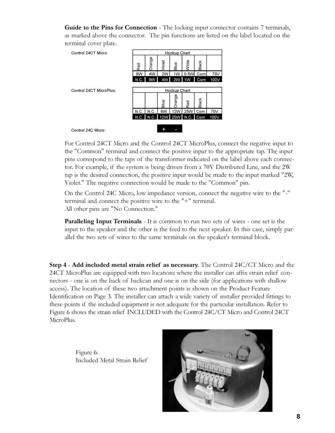
The speaker also features a built-in transformer with multiple tapping options that facilitate easy integration into commercial 70V/100V distributed audio systems. This feature is particularly advantageous for large venues, where long cable runs and multiple speakers are common. The transformer is designed to allow for the adjustment of power output, catering to the specific needs of each installation.
Durability is a priority for the JBL 24C/CT, which is constructed with high-quality materials that withstand the rigors of commercial use. The speaker’s grille is made from rust-resistant materials, ensuring a long lifespan even in challenging environments.
Overall, the JBL 24C/CT is an outstanding choice for anyone in need of reliable, high-quality ceiling speakers. Its blend of powerful sound capabilities, innovative technologies, and practical design makes it a go-to solution for any professional audio installation. Whether for background music or announcements, the JBL 24C/CT delivers consistent and impressive performance that meets the demands of modern commercial spaces.

