•Always wear protective eyewear when using tools.
•When routing cables, keep input signal cables away from power cables and speaker wires.
•When making connections, make sure that each connection is clean, insulated and properly secured. Observe the polarity markings on the rear panel. Refer to the application drawings to set up the amplifier for operation in stereo,
•If the amplifier’s fuse must be replaced, use only the same rating and type as a replacement. Do not substitute another kind.
|
|
|
|
|
|
|
|
|
| |
| 4 |
|
|
|
| 5 |
|
| 6 | |
|
|
|
|
| MADE IN THE U.S.A. |
|
|
|
| |
|
|
| SPEAKER OUTPUTS |
|
|
|
| POWER |
| |
|
|
| BRIDGE |
|
| FUSE |
|
| ||
| – | L | +– | R | + | 30A |
| +BATT | REM | GND |
|
|
|
|
|
| 0 |
|
|
|
|
|
|
|
|
|
| 3 |
|
|
|
|
| 1 |
|
|
|
|
|
| 2 |
| 3 |
| LINE LEVEL |
|
|
|
|
| SPEAKER LEVEL IN | AUX | ||
| INPUT |
|
|
|
|
|
| OUT | ||
|
|
|
|
|
|
|
| + | + |
|
| L |
|
|
|
|
|
| R | L | L |
|
|
|
|
|
|
|
| – | – |
|
| R |
|
|
|
|
|
|
|
| R |
| 8 | 11 |
|
|
|
| 9 |
|
| |
| 2V |
|
|
| 80Hz |
|
|
|
|
|
INPUT MODE | XOVER |
|
| PRE OUT |
|
| ||||
MO ST | LP |
| HP FLAT |
|
| LP | HP FLAT |
|
| |
| 4V LEVEL .250V |
|
| 32Hz FREQ 320Hz |
|
|
|
|
| |
712
|
|
|
|
|
|
|
|
|
|
|
|
| ||
4 |
|
|
|
| 6 |
|
|
| 5 |
|
|
|
|
|
|
|
|
| MADE IN THE U.S.A. |
|
|
|
|
|
|
|
|
| |
|
| SPEAKER OUTPUTS |
| POWER |
|
|
|
|
|
|
|
| ||
FRONT | – | BRIDGE | + |
| FUSE | FUSE |
|
|
|
|
| |||
| L + | – R | +BATT | REM | GND |
|
|
|
|
| ||||
|
|
|
|
| 30A | 30A |
|
|
|
|
| |||
|
|
|
|
|
|
|
| 30 | 30 |
|
|
|
|
|
REAR |
| BRIDGE |
|
|
|
|
|
|
|
|
|
|
| |
1 |
|
|
|
|
|
| 2 |
|
|
| 3 |
|
|
|
|
|
|
|
|
|
|
|
|
|
|
|
| ||
| LINE LEVEL |
|
|
|
| SPKR LEVEL IN |
|
|
|
|
|
| ||
| FRONT | INPUT |
|
|
|
| REAR | AUX |
|
|
|
|
| |
| REAR |
|
|
|
| +R– | OUT |
|
|
|
|
| ||
L |
|
|
|
|
|
|
|
| L |
|
|
|
|
|
|
|
|
|
|
|
| +R– |
|
|
|
|
|
| |
R |
|
|
|
|
|
| FRONT | R |
|
|
|
|
| |
|
|
|
|
|
|
|
|
|
|
|
|
| ||
8 |
|
| 12 |
|
|
| 10 |
| 12 |
|
| 8 | 7 | |
2V | FRONT | XOVER | 80Hz | PRE OUT |
|
| 80Hz | XOVER | REAR | 2V |
| |||
INPUT MODE |
| XOVER | AMP |
| F+R | REAR FRT | INPUT |
|
| AMP XOVER | INPUT MODE | |||
MO ST |
| FLAT HP | LP |
| FLAT | LP | LP | FRT REAR |
| FLAT HP LP | ST | MO | ||
6V LEVEL .250V |
| 32Hz |
| 320Hz |
|
|
| 32Hz | 320Hz |
| 4V LEVEL .250V |
| ||
7540 |
|
|
|
|
|
|
|
|
|
|
|
|
|
|
11 |
|
| 9 |
|
|
|
|
| 11 |
|
|
|
| |
7 |
|
|
|
|
|
|
|
|
|
|
|
|
|
|
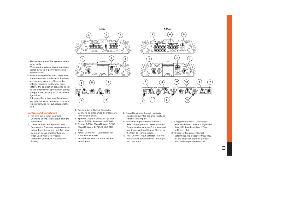
Controls and Connectors
1.
2.Universal Interface Speaker Level Connector – Connects to
3.
4.
5.Fuses –
30A ATC type x 2,
6.Power Connector – Connection for 12V+, Gnd and Rem.
7.
8.Input Sensitivity Control – Adjusts input sensitivity for
9.
the front or rear crossover.
10.
11.Crossover Selector – Determines whether the crossover is a
12.Crossover Frequency Control – Determines the crossover frequency for the amplifier channels (front or rear) and the
3