P-2510
4 |
|
|
| 5 |
|
| 6 | 1 |
|
| 2 |
|
|
|
|
|
|
|
| ||||
|
|
|
| MADE IN THE U.S.A. |
|
|
|
|
|
|
|
| SPEAKER OUTPUTS |
|
|
|
|
| LINE LEVEL | UNIVERSAL INTERFACE | |||
+ | + | – | – | FUSE |
| POWER |
|
| INPUT |
| REAR |
+BATT |
| FRONT | REAR | + R – | – L + | ||||||
|
|
|
| 40A | REM | GND |
|
|
|
| |
|
|
|
|
|
|
|
| L |
|
|
|
|
|
|
| 40 |
|
|
|
|
| + R – | – L + |
|
|
|
|
|
|
|
| R |
| FRONT | |
8 | 12 |
| |
2V | 80Hz |
4V LEVEL .250V | 32Hz FREQ 320Hz |
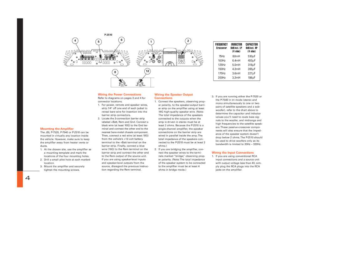
FREQUENCY | INDUCTOR | CAPACITOR |
Crossover | 6dB/oct. LP | 6dB/oct. HP |
| (4 ohm) | (4 ohm) |
75Hz | 8.0mH | 530µF |
100Hz | 6.4mH | 400µF |
125Hz | 5.0mH | 318µF |
150Hz | 4.2mH | 265µF |
175Hz | 3.6mH | 227µF |
200Hz | 3.2mH | 198µF |
|
|
|
Mounting the Amplifier
The JBL
1.At the chosen site, use the amplifier as a mounting template and mark the locations of the four mounting holes.
2.Drill a small pilot hole at each marked location.
3.Mount the amplifier and securely tighten the mounting screws.
Wiring the Power Connections
Refer to diagrams on pages 3 and 4 for connector locations.
1.For power, remote and speaker wires, strip 1⁄4" off one end of each jacket to reveal bare wire for insertion into the barrier strip connectors.
2.Locate the
Wiring the Speaker Output Connections
1.Connect the speakers, observing prop- er polarity, to the
16G
2.If you are bridging the amplifier, con- nect the speaker wires to the termi- nals marked “bridge,” observing prop- er polarity. (Note: The total impedance of the speaker system to be connected to the amplifier must be at least 4 ohms in bridge mode.)
3.If you are running either the
Wiring the Input Connections
1.If you are using conventional RCA input connections and a source unit with output voltage less than 4V, sim- ply plug the RCA plugs into the RCA jacks on the amplifier.
4