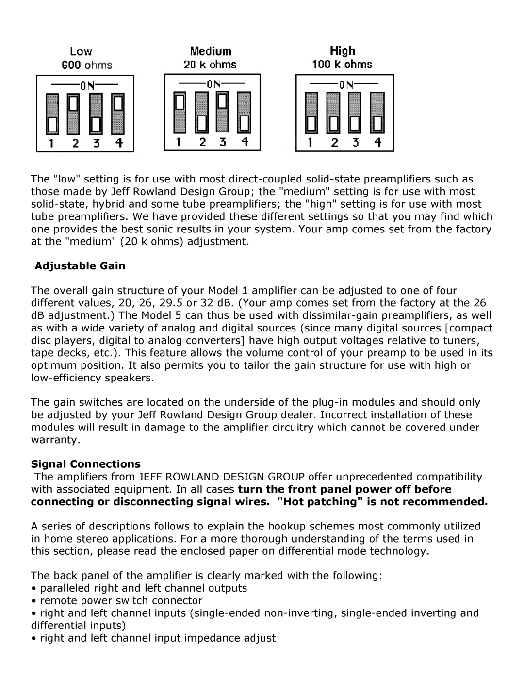
The "low" setting is for use with most direct-coupled solid-state preamplifiers such as those made by Jeff Rowland Design Group; the "medium" setting is for use with most solid-state, hybrid and some tube preamplifiers; the "high" setting is for use with most tube preamplifiers. We have provided these different settings so that you may find which one provides the best sonic results in your system. Your amp comes set from the factory at the "medium" (20 k ohms) adjustment.
Adjustable Gain
The overall gain structure of your Model 1 amplifier can be adjusted to one of four different values, 20, 26, 29.5 or 32 dB. (Your amp comes set from the factory at the 26 dB adjustment.) The Model 5 can thus be used with dissimilar-gain preamplifiers, as well as with a wide variety of analog and digital sources (since many digital sources [compact disc players, digital to analog converters] have high output voltages relative to tuners, tape decks, etc.). This feature allows the volume control of your preamp to be used in its optimum position. It also permits you to tailor the gain structure for use with high or low-efficiency speakers.
The gain switches are located on the underside of the plug-in modules and should only be adjusted by your Jeff Rowland Design Group dealer. Incorrect installation of these modules will result in damage to the amplifier circuitry which cannot be covered under warranty.
Signal Connections
The amplifiers from JEFF ROWLAND DESIGN GROUP offer unprecedented compatibility with associated equipment. In all cases turn the front panel power off before connecting or disconnecting signal wires. "Hot patching" is not recommended.
A series of descriptions follows to explain the hookup schemes most commonly utilized in home stereo applications. For a more thorough understanding of the terms used in this section, please read the enclosed paper on differential mode technology.
The back panel of the amplifier is clearly marked with the following:
•paralleled right and left channel outputs
•remote power switch connector
•right and left channel inputs (single-ended non-inverting, single-ended inverting and differential inputs)
•right and left channel input impedance adjust

