CD1211
WIRING
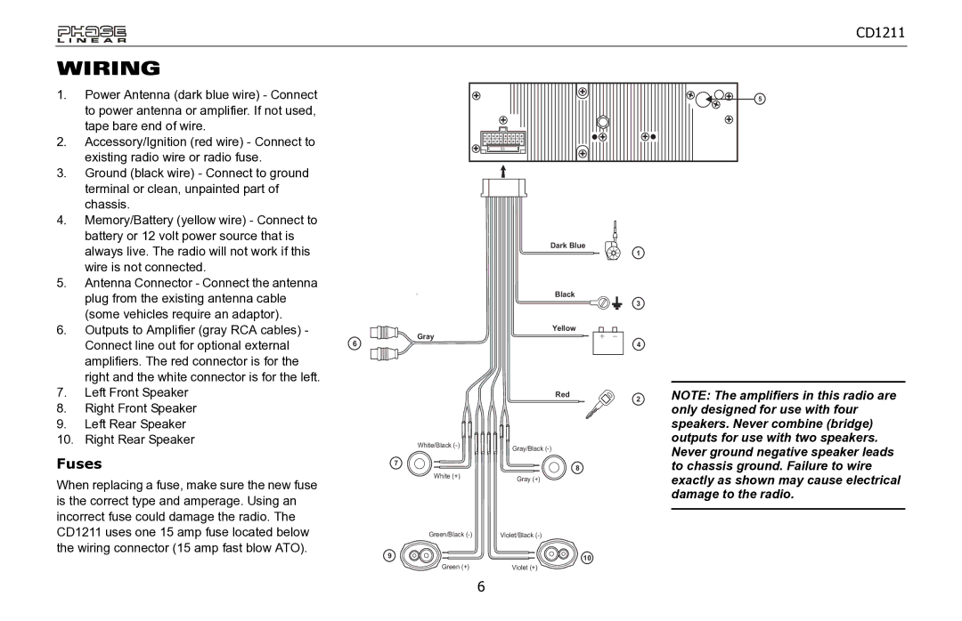
1. Power Antenna (dark blue wire) - Connect to power antenna or amplifier. If not used, tape bare end of wire.
2.Accessory/Ignition (red wire) - Connect to existing radio wire or radio fuse.
3.Ground (black wire) - Connect to ground
terminal or clean, unpainted part of chassis.
5
15
4. | Memory/Battery (yellow wire) - Connect to |
|
| battery or 12 volt power source that is |
|
| always live. The radio will not work if this |
|
| wire is not connected. |
|
5. | Antenna Connector - Connect the antenna |
|
| plug from the existing antenna cable |
|
| (some vehicles require an adaptor). |
|
6. | Outputs to Amplifier (gray RCA cables) - | Gray |
| Connect line out for optional external | |
| 6 | |
|
| |
| amplifiers. The red connector is for the |
|
| right and the white connector is for the left. |
|
7.Left Front Speaker
8.Right Front Speaker
9. Left Rear Speaker
10. Right Rear Speaker
White/Black
Fuses | 7 |
When replacing a fuse, make sure the new fuse | White (+) |
| |
is the correct type and amperage. Using an |
|
incorrect fuse could damage the radio. The |
|
CD1211 uses one 15 amp fuse located below | Green/Black |
the wiring connector (15 amp fast blow ATO). | 9 |
| |
| Green (+) |
Dark Blue
Black
Yellow
+
Red
Gray/Black
8
Gray (+)
Violet/Black
10
Violet (+)
1
3
4
2
NOTE: The amplifiers in this radio are only designed for use with four speakers. Never combine (bridge) outputs for use with two speakers. Never ground negative speaker leads to chassis ground. Failure to wire exactly as shown may cause electrical damage to the radio.
6