Extension Cords
Make sure your extension cord is in good condition. When using an extension cord, be sure to use one heavy enough to carry the current your machine will draw. An undersized cord will cause a drop in the line voltage resulting in power loss and overheating. Table 1 shows the correct size to use depending on the cord length and nameplate ampere rating. If in doubt, use the next heavier gauge. Remember, the smaller the gauge number, the heavier the cord.
Recommended Extension Cord Gauges
Amps | Extension Cord Length in Feet * |
| |||||
|
|
|
|
|
|
| |
| 25 | 50 | 75 | 100 | 150 |
| 200 |
|
|
|
|
|
|
|
|
< 5 | 16 | 16 | 16 | 14 | 12 |
| 12 |
|
|
|
|
|
|
|
|
5 to 8 | 16 | 16 | 14 | 12 | 10 |
| NR |
|
|
|
|
|
|
|
|
8 to 12 | 14 | 14 | 12 | 10 | NR |
| NR |
|
|
|
|
|
|
|
|
12 to 15 | 12 | 12 | 10 | 10 | NR |
| NR |
|
|
|
|
|
|
|
|
15 to 20 | 10 | 10 | 10 | NR | NR |
| NR |
|
|
|
|
|
|
|
|
21 to 30 | 10 | NR | NR | NR | NR |
| NR |
|
|
|
|
|
|
|
|
*based on limiting the line voltage drop to 5V at 150% of the rated amperes.
NR: Not Recommended.
Table 1
Adjustments
Sanding Platen Angle Adjustment
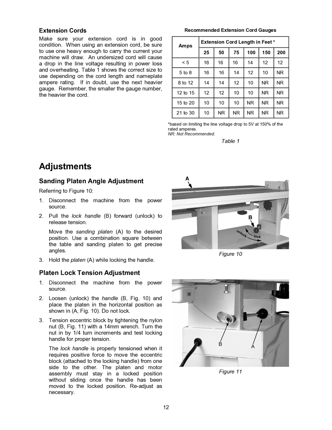
Referring to Figure 10:
1.Disconnect the machine from the power source.
2.Pull the lock handle (B) forward (unlock) to release tension.
Move the sanding platen (A) to the desired position. Use a combination square between the table and sanding platen to get precise angles.
3.Hold the platen (A) while locking the handle.
Platen Lock Tension Adjustment
1.Disconnect the machine from the power source.
2.Loosen (unlock) the handle (B, Fig. 10) and place the platen in the horizontal position as shown in (A, Fig. 10). Do not lock.
3.Tension eccentric block by tightening the nylon nut (B, Fig. 11) with a 14mm wrench. Turn the nut in by 1/4 turn increments and test locking handle for proper tension.
The lock handle is properly tensioned when it requires positive force to move the eccentric block (attached to the locking handle) from one side to the other. The platen and motor assembly must stay in a locked position without sliding once the handle has been moved to the locked position.
Figure 10
Figure 11
12
