JL Audio C3-570-XO, C3-570cw Wiring Your Speaker System, Diagram a Component System Wiring

Models: C3-570-031010 C3-570cw C3-570-XO C3-570

1 16
Download 16 pages 38.37 Kb
Page 5
Image 5

WIRING YOUR SPEAKER SYSTEM

C3 Convertible Components give you the option of installing the speakers as separate component speaker systems or as coaxial systems (tweeters mounted onto the center of each woofer).

Positive (+) and negative (–) connections to the crossover from the amplifier outputs are made with the terminals labeled “IN+” and IN–”. The Positive and Negative outputs to the woofer connections are labeled “W+” and W–”on the Crossover and should be connected to corresponding “WFR+” and  WFR– terminals on the woofer (as illustrated below). The tweeter connections vary by system configuration and may be made in one of two ways.

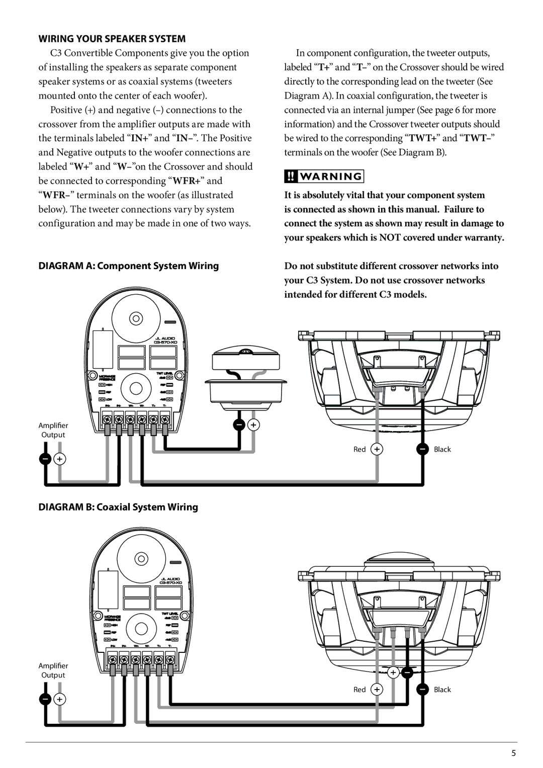
Diagram A: Component System Wiring

In component configuration, the tweeter outputs, labeled “T+” and T– on the Crossover should be wired directly to the corresponding lead on the tweeter (See Diagram A). In coaxial configuration, the tweeter is connected via an internal jumper (See page 6 for more information) and the Crossover tweeter outputs should be wired to the corresponding “TWT+” and TWT– terminals on the woofer (See Diagram B).

!! WARNING

It is absolutely vital that your component system is connected as shown in this manual. Failure to connect the system as shown may result in damage to your speakers which is NOT covered under warranty.

Do not substitute different crossover networks into your C3 System. Do not use crossover networks intended for different C3 models.

Amplifier

Output

Red

Black

Diagram B: Coaxial System Wiring

Amplifier

Output

Red

Black

5

Page 5
Image 5
JL Audio C3-570-XO Wiring Your Speaker System, Diagram a Component System Wiring, Diagram B Coaxial System Wiring