JL Audio J21000.1 owner manual REMote turn-On, Amplifier InputS

Models: J21000.1

1 11
Download 11 pages 57.04 Kb
Page 4
Image 4

“REMote” turn-On

The J2-1000.1 is turned on and off using a conventional +12V remote turn- on lead, typically controlled by the source unit’s remote turn-on output.

Ground

Remote

+ ��VDC

35A

The amplifier will turn on when +12V is

present at its “Remote” input and turn off when

+12V is switched off. If a source unit does not

have a dedicated remote turn-on output, the amplifier’s turn-on lead can be connected to +12V via a switch that derives power from an ignition- switched circuit.

18 AWG wire is more than adequate for the remote
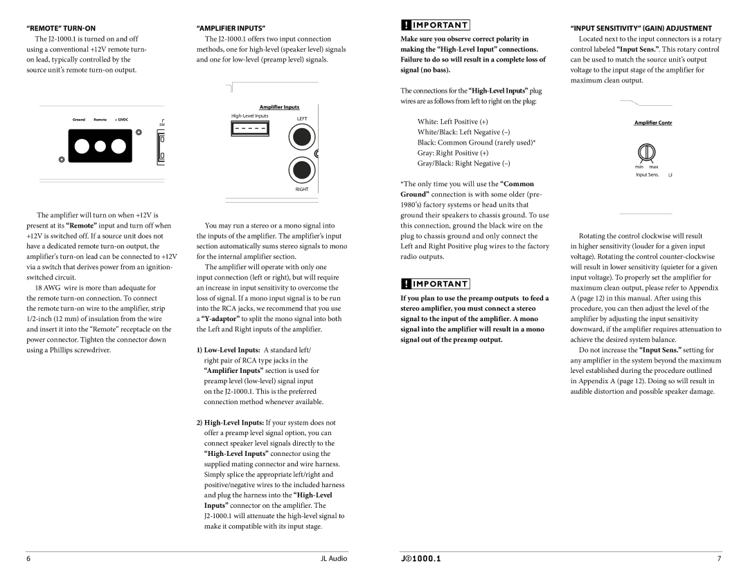
 turn-on connection. To connect the remote turn-on wire to the amplifier, strip 1/2-inch (12 mm) of insulation from the wire and insert it into the “Remote” receptacle on the power connector. Tighten the connector down using a Phillips screwdriver.

“AMPLIFIER InputS”

The J2-1000.1 offers two input connection methods, one for high-level (speaker level) signals and one for low-level (preamp level) signals.

Amplifier Inputs

High-Level Inputs

LEFT


RIGHT

You may run a stereo or a mono signal into the inputs of the amplifier. The amplifier’s input section automatically sums stereo signals to mono for the internal amplifier section.

The amplifier will operate with only one input connection (left or right), but will require an increase in input sensitivity to overcome the loss of signal. If a mono input signal is to be run into the RCA jacks, we recommend that you use a “Y-adaptor”to split the mono signal into both the Left and Right inputs of the amplifier.

1)Low-Level Inputs: A standard left/ right pair of RCA type jacks in the “Amplifier Inputs” section is used for preamp level (low-level) signal input on the J2-1000.1. This is the preferred connection method whenever available.

2)High-Level Inputs: If your system does not offer a preamp level signal option, you can connect speaker level signals directly to the “High-Level Inputs” connector using the supplied mating connector and wire harness. Simply splice the appropriate left/right and positive/negative wires to the included harness and plug the harness into the “High-Level Inputs” connector on the amplifier. The

J2-1000.1 will attenuate the high-level signal to make it compatible with its input stage.

! IMPORTANT

Make sure you observe correct polarity in making the “High-Level Input” connections. Failure to do so will result in a complete loss of signal (no bass).

The connections for the “High-Level Inputs” plug wires are as follows from left to right on the plug:

White: Left Positive (+)

White/Black: Left Negative (–)

Black: Common Ground (rarely used)*

Gray: Right Positive (+)

Gray/Black: Right Negative (–)

*The only time you will use the “Common Ground” connection is with some older (pre- 1980’s) factory systems or head units that ground their speakers to chassis ground. To use this connection, ground the black wire on the plug to chassis ground and only connect the Left and Right Positive plug wires to the factory radio outputs.

! IMPORTANT

If you plan to use the preamp outputs to feed a stereo amplifier, you must connect a stereo signal to the input of the amplifier. A mono signal into the amplifier will result in a mono signal out of the preamp output.

“INPUT SENSITIVITY” (GAIN) ADJUSTMENT Located next to the input connectors is a rotary

control labeled “Input Sens.”. This rotary control can be used to match the source unit’s output voltage to the input stage of the amplifier for maximum clean output.

Amplifier Contr

min max

Input Sens. LP

Rotating the control clockwise will result in higher sensitivity (louder for a given input voltage). Rotating the control counter-clockwise will result in lower sensitivity (quieter for a given input voltage). To properly set the amplifier for maximum clean output, please refer to Appendix A (page 12) in this manual. After using this procedure, you can then adjust the level of the amplifier by adjusting the input sensitivity downward, if the amplifier requires attenuation to achieve the desired system balance.

Do not increase the “Input Sens.” setting for any amplifier in the system beyond the maximum level established during the procedure outlined in Appendix A (page 12). Doing so will result in audible distortion and possible speaker damage.

6

JL Audio

7

Page 4
Image 4
JL Audio J21000.1 owner manual REMote turn-On, Amplifier InputS