! ! | CAUTION | ! ! |
|
|
|
While this speaker is designed to be water and spray resistant, it is not designed to be submerged or to withstand
Prolonged exposure to sound pressure levels in excess of 100dB can cause permanent hearing loss. This
When installing a subwoofer in your vessel, it is extremely important to secure it firmly. This applies not only to the woofer itself, but also the structure it is mounted to. If not firmly attached, the speaker can become a dangerous projectile in a collision. Please review the mounting information carefully and use the supplied
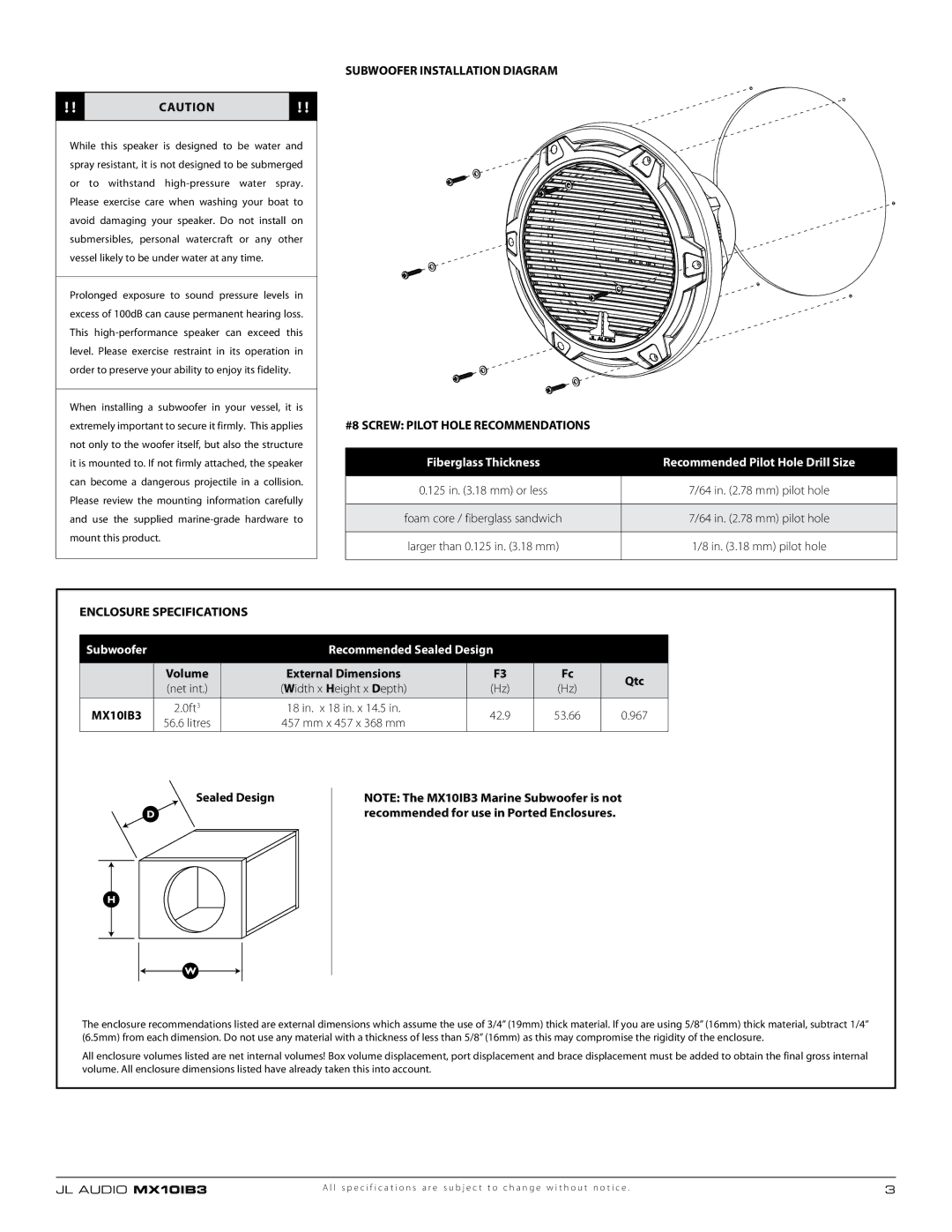
SUBWOOFER INSTALLATION DIAGRAM
#8 SCREW: PILOT HOLE RECOMMENDATIONS
Fiberglass Thickness | Recommended Pilot Hole Drill Size |
|
|
0.125 in. (3.18 mm) or less | 7/64 in. (2.78 mm) pilot hole |
|
|
foam core / fiberglass sandwich | 7/64 in. (2.78 mm) pilot hole |
|
|
larger than 0.125 in. (3.18 mm) | 1/8 in. (3.18 mm) pilot hole |
|
|
ENCLOSURE SPECIFICATIONS
Subwoofer |
| Recommended Sealed Design |
|
| ||
|
|
|
|
|
| |
| Volume | External Dimensions | F3 | Fc | Qtc | |
| (net int.) | (Width x Height x Depth) | (Hz) | (Hz) | ||
|
| |||||
|
|
|
|
|
| |
MX10IB3 | 2.0ft3 | 18 in. x 18 in. x 14.5 in. | 42.9 | 53.66 | 0.967 | |
56.6 litres | 457 mm x 457 x 368 mm | |||||
|
|
|
| |||
Sealed Design
NOTE: The MX10IB3 Marine Subwoofer is not recommended for use in Ported Enclosures.
The enclosure recommendations listed are external dimensions which assume the use of 3/4” (19mm) thick material. If you are using 5/8” (16mm) thick material, subtract 1/4” (6.5mm) from each dimension. Do not use any material with a thickness of less than 5/8” (16mm) as this may compromise the rigidity of the enclosure.
All enclosure volumes listed are net internal volumes! Box volume displacement, port displacement and brace displacement must be added to obtain the final gross internal volume. All enclosure dimensions listed have already taken this into account.
JL AUDIO MX10IB3 | A l l s p e c i f i c a t i o n s a r e s u b j e c t t o c h a n g e w i t h o u t n o t i c e . | 3 |