PHYSICAL SPECIFICATIONS
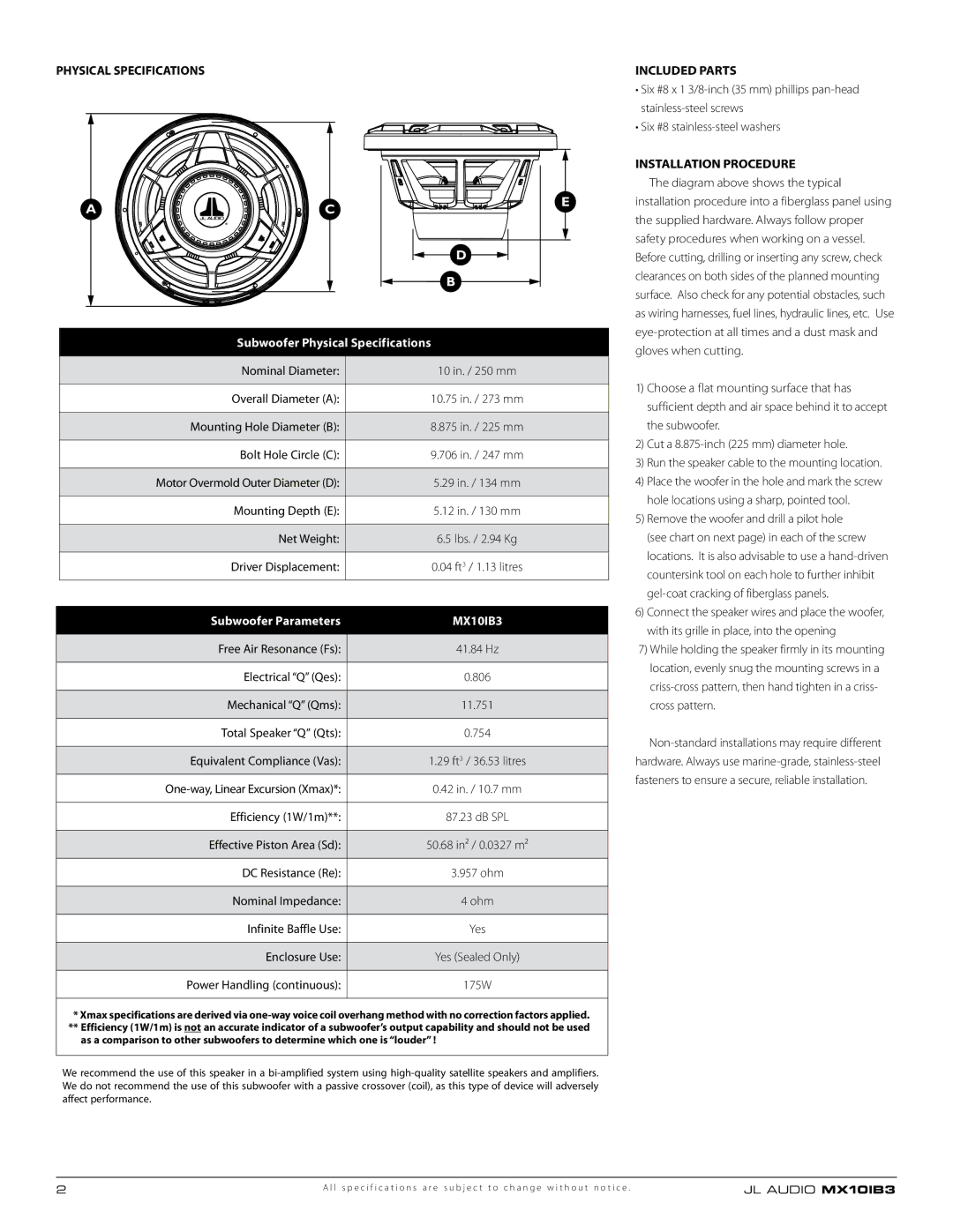
A
C
D
B
E
INCLUDED PARTS
•Six #8 x 1
•Six #8
INSTALLATION PROCEDURE
The diagram above shows the typical installation procedure into a fiberglass panel using the supplied hardware. Always follow proper safety procedures when working on a vessel. Before cutting, drilling or inserting any screw, check clearances on both sides of the planned mounting surface. Also check for any potential obstacles, such as wiring harnesses, fuel lines, hydraulic lines, etc. Use
Subwoofer Physical Specifications
| Nominal Diameter: | 10 in. / 250 mm |
|
|
|
| Overall Diameter (A): | 10.75 in. / 273 mm |
|
|
|
| Mounting Hole Diameter (B): | 8.875 in. / 225 mm |
|
|
|
| Bolt Hole Circle (C): | 9.706 in. / 247 mm |
|
|
|
| Motor Overmold Outer Diameter (D): | 5.29 in. / 134 mm |
|
|
|
| Mounting Depth (E): | 5.12 in. / 130 mm |
|
|
|
| Net Weight: | 6.5 lbs. / 2.94 Kg |
|
|
|
| Driver Displacement: | 0.04 ft3 / 1.13 litres |
|
|
|
|
|
|
| Subwoofer Parameters | MX10IB3 |
|
|
|
| Free Air Resonance (Fs): | 41.84 Hz |
|
|
|
| Electrical “Q” (Qes): | 0.806 |
|
|
|
| Mechanical “Q” (Qms): | 11.751 |
|
|
|
| Total Speaker “Q” (Qts): | 0.754 |
|
|
|
| Equivalent Compliance (Vas): | 1.29 ft3 / 36.53 litres |
|
|
|
| 0.42 in. / 10.7 mm | |
|
|
|
| Efficiency (1W/1m)**: | 87.23 dB SPL |
|
|
|
| Effective Piston Area (Sd): | 50.68 in² / 0.0327 m² |
|
|
|
| DC Resistance (Re): | 3.957 ohm |
|
|
|
| Nominal Impedance: | 4 ohm |
|
|
|
| Infinite Baffle Use: | Yes |
|
|
|
| Enclosure Use: | Yes (Sealed Only) |
|
|
|
| Power Handling (continuous): | 175W |
|
|
|
*Xmax specifications are derived via
**Efficiency (1W/1m) is not an accurate indicator of a subwoofer’s output capability and should not be used as a comparison to other subwoofers to determine which one is “louder” !
We recommend the use of this speaker in a
gloves when cutting.
1)Choose a flat mounting surface that has sufficient depth and air space behind it to accept the subwoofer.
2)Cut a
3)Run the speaker cable to the mounting location.
4)Place the woofer in the hole and mark the screw hole locations using a sharp, pointed tool.
5)Remove the woofer and drill a pilot hole (see chart on next page) in each of the screw locations. It is also advisable to use a
6)Connect the speaker wires and place the woofer, with its grille in place, into the opening
7)While holding the speaker firmly in its mounting location, evenly snug the mounting screws in a
2 | A l l s p e c i f i c a t i o n s a r e s u b j e c t t o c h a n g e w i t h o u t n o t i c e . | JL AUDIO MX10IB3 |