S T E P 1 2
With the bottom of the Custom Bracket bolted in and aligned as described in Step 11 drill a hole through the pillar corresponding with the upper hole in the Custom Bracket as shown.
****CAUTION****
Before drilling, always make sure that you are not going to be drilling into any gas lines, brake lines, tires, transmission lines, electrical wiring, exhaust systems or anything else that might cause a reduction in your weekly pay. Always wear eye protection when drilling!
S T E P 1 3
From inside the rear pillar, feed the
A suggestion on how to get the hardware through the hole and held in place is shown below.
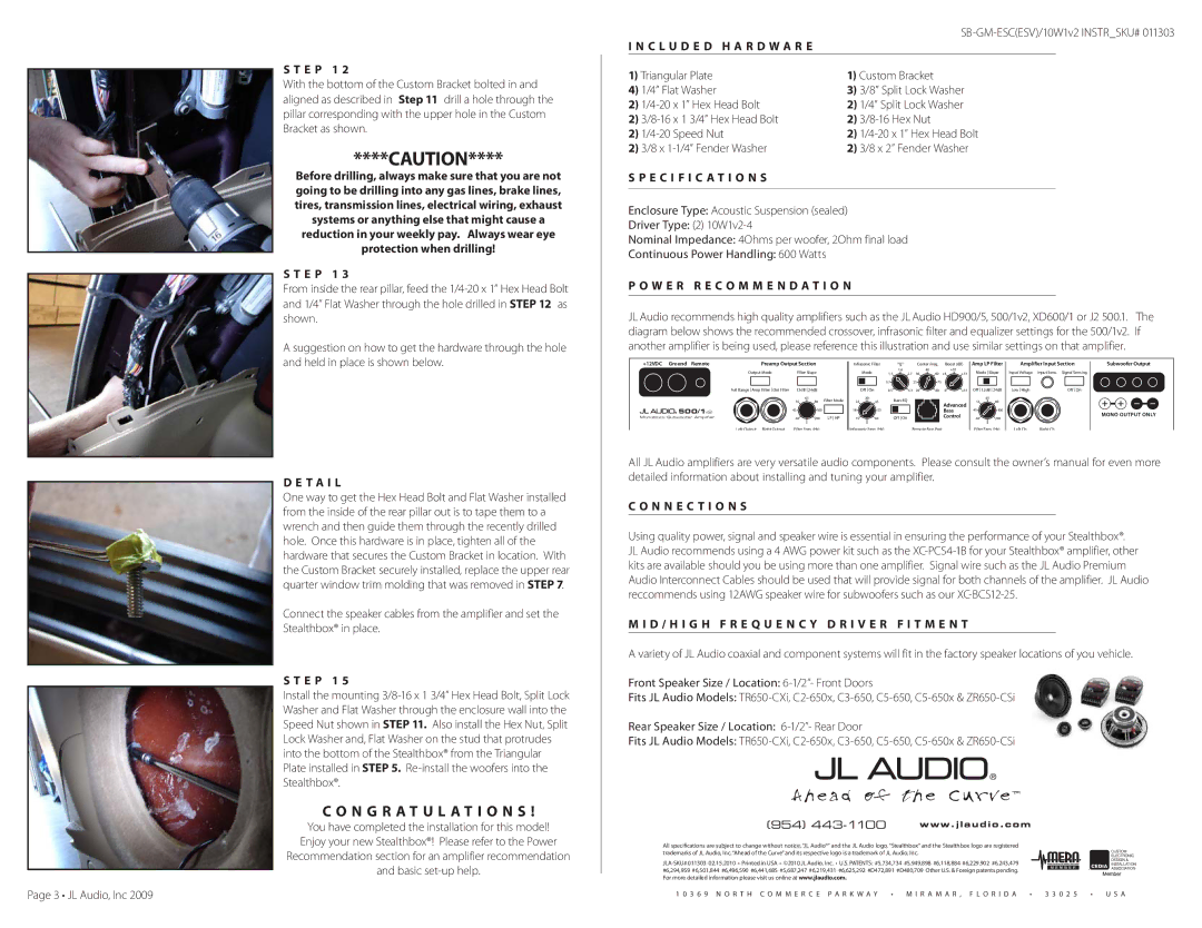
D E T A I L
One way to get the Hex Head Bolt and Flat Washer installed from the inside of the rear pillar out is to tape them to a wrench and then guide them through the recently drilled hole. Once this hardware is in place, tighten all of the hardware that secures the Custom Bracket in location. With the Custom Bracket securely installed, replace the upper rear quarter window trim molding that was removed in STEP 7.
Connect the speaker cables from the amplifier and set the Stealthbox® in place.
S t e p 1 5
Install the mounting
C O N G R A T U L A T I O N S !
You have completed the installation for this model! Enjoy your new Stealthbox®! Please refer to the Power Recommendation section for an amplifier recommendation and basic
I N C L U D E D H A R D W A R E
1) Triangular Plate | 1) Custom Bracket | ||
4) | 1/4” Flat Washer | 3) 3/8” Split Lock Washer | |
2) | 2) | 1/4” Split Lock Washer | |
2) | 2) | ||
2) | 2) | ||
2) | 3/8 x | 2) 3/8 x 2” Fender Washer | |
S P E C I F I C A T I O N S
Enclosure Type: Acoustic Suspension (sealed)
Driver Type: (2)
Nominal Impedance: 4Ohms per woofer, 2Ohm final load
Continuous Power Handling: 600 Watts
P o w e r R e c o m m e n d a t i o n
JL Audio recommends high quality amplifiers such as the JL Audio HD900/5, 500/1v2, XD600/1 or J2 500.1. The diagram below shows the recommended crossover, infrasonic filter and equalizer settings for the 500/1v2. If another amplifier is being used, please reference this illustration and use similar settings on that amplifier.
+12VDC Ground Remote | Preamp Output Section | Infrasonic Filter | “Q” | Center Freq. Boost (dB) Amp LP Filter | Amplifier Input Section | Subwoofer Output |
Output Mode | Filter Slope |
| Mode |
| 1.6 |
| 40 | +10 |
| Mode Slope | Input Voltage | Input Sens. | Signal Sensing | ||
| 1.1 | 2.7 | 30 | 60 | +4 | +13 | |||||||||
|
|
|
|
| 0.7 |
| 25 | 75 |
|
|
|
|
|
|
|
Full Range Amp Filter Out Filter | 12dB 24dB |
| Off On | 0.5 | 4.3 | 20 | 80 | 0 | +15 | Off 12dB 24dB | Low High |
| Off On | ||
|
| 65 | Filter Mode | 30 |
| Bass EQ |
|
|
|
|
| 65 |
|
|
|
| 55 | 80 | 22 | 45 |
|
| Advanced | 55 | 80 |
|
|
| |||
500/1v2 |
|
|
|
|
|
|
|
|
|
|
|
|
| ||
45 | 100 |
| 18 | 55 |
|
|
| Bass |
| 45 | 100 |
|
| MONO OUTPUT ONLY | |
Monoblock Subwoofer Amplifier | 40 | 200 | LP HP | 15 | 60 | Off On |
|
| Control |
| 40 | 200 |
|
| |
Left Output Right Output | Filter Freq. (Hz) | Infrasonic Freq. (Hz) | Remote Bass Port | Filter Freq. (Hz) | Left Ch. | Right Ch. |
All JL Audio amplifiers are very versatile audio components. Please consult the owner’s manual for even more detailed information about installing and tuning your amplifier.
C o n n e c t i o n s
Using quality power, signal and speaker wire is essential in ensuring the performance of your Stealthbox®. JL Audio recommends using a 4 AWG power kit such as the
M I D / H I G H F r e q u e n c y D r i v e r F I T M E N T
A variety of JL Audio coaxial and component systems will fit in the factory speaker locations of you vehicle.
Front Speaker Size / Location:
Fits JL Audio Models:
Rear Speaker Size / Location:
Fits JL Audio Models:
(954) | www.jlaudio.com |
All specifications are subject to change without notice. “JL Audio®” and the JL Audio logo, “Stealthbox” and the Stealthbox logo are registered trademarks of JL Audio, Inc. “Ahead of the Curve” and its respective logo is a trademark of JL Audio, Inc.
Page 3 • JL Audio, Inc 2009
1 0 3 6 9 N O R T H C O M M E R C E P A R K W A Y • M I R A M A R , F L O R I D A • 3 3 0 2 5 • U S A