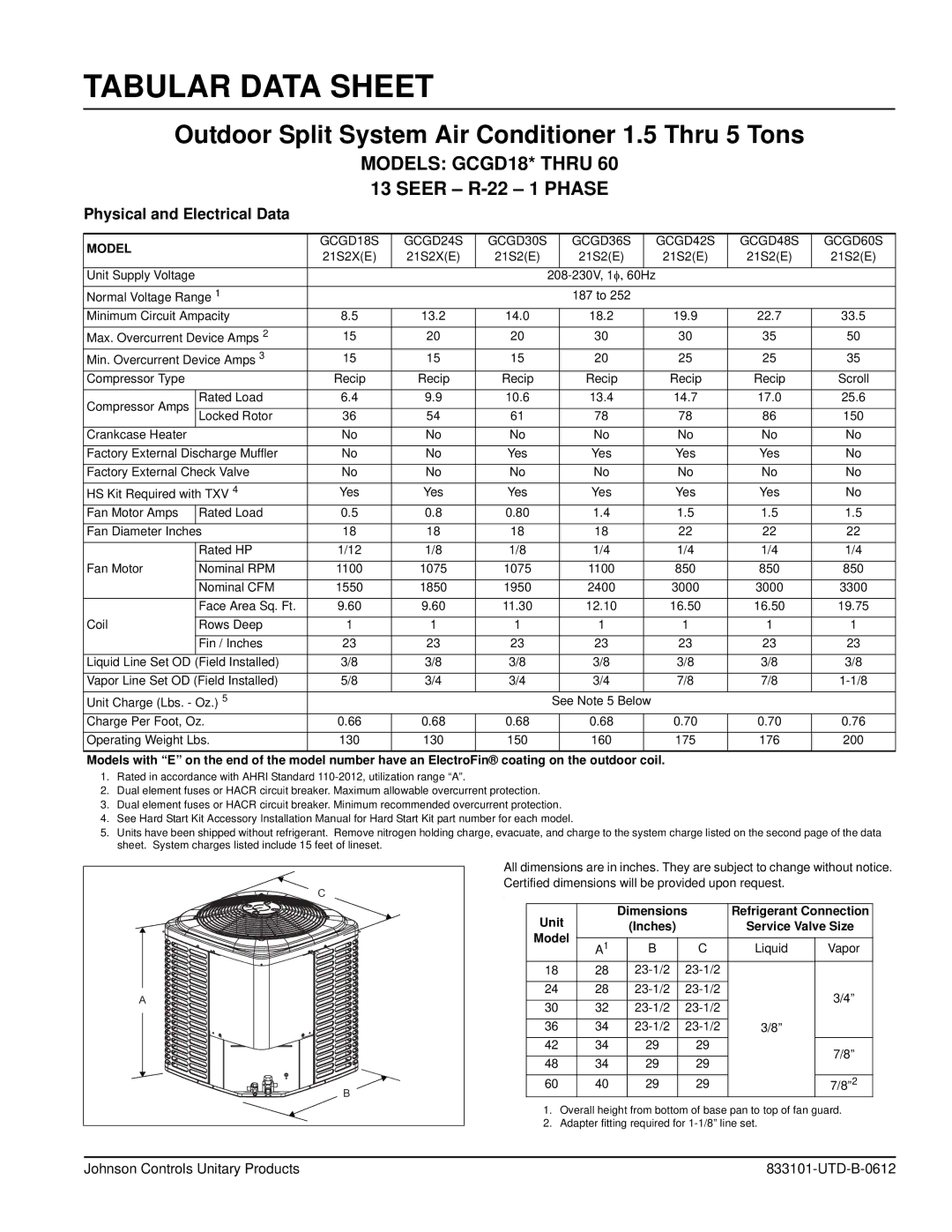
GCGD18 thru 60 specifications
Johnson Controls is known for its innovative solutions in building efficiency and energy management, and the GCGD series, with models ranging from 18 to 60, exemplifies this commitment. These rooftop units offer a versatile and reliable option for commercial heating and cooling applications, combining advanced technology with robust performance.One of the standout features of the GCGD series is its high-efficiency scroll compressors, which provide dependable cooling and heating without sacrificing energy efficiency. These compressors enable the units to achieve high Seasonal Energy Efficiency Ratio (SEER) ratings, catering to the growing demand for lower operational costs and reduced environmental impact.
The GCGD series incorporates multiple stages of heating and cooling, ensuring that these systems can precisely meet the varying demands of commercial spaces. The variable-speed blower motors allow for improved airflow management, ensuring optimal comfort levels while minimizing energy use. In addition to this, the embedded controls offer intuitive operation and monitoring capabilities, empowering facility managers with real-time data and analytics for enhanced decision-making.
Another notable characteristic of the GCGD series is its modular design. This flexibility allows for easy installation and maintenance, ensuring minimal downtime during service. The units can be configured for both ducted and non-ducted applications, making them suitable for a range of commercial settings, from retail spaces to office buildings.
The GCGD series also integrates advanced refrigerant technology. Equipped with the capacity to use environmentally friendly refrigerants, these units align with global standards for sustainability and energy efficiency. The incorporation of direct drive fans further enhances energy savings, reducing mechanical wear and tear while improving quiet operation.
The GCGD series is built with reliability in mind, featuring durable construction materials that withstand the challenges of various climates. With rigorous testing and validation, Johnson Controls has ensured that these units deliver consistent performance over time, making them a trusted choice for facility managers.
In conclusion, the Johnson Controls GCGD series, ranging from 18 to 60, embodies a perfect blend of efficiency, durability, and adaptability, making it an ideal solution for those seeking reliable heating and cooling solutions in commercial environments. With its advanced technologies, intelligent controls, and focus on sustainability, the GCGD series is paving the way for a more efficient future in HVAC systems.