10.Braze the line set to the units
11.Leak check refrigerant lines and indoor coil connections. If leak free, remove leak check charge, reinstall any Schraeder cores that were removed from the outdoor unit and evacuate refrigerant lines and ID coil. Evacuate through the Schraeder access valves of the liquid and vapor service valves on OD unit.
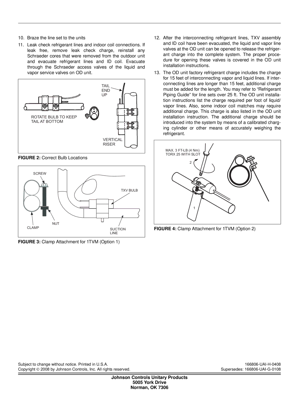
TAIL
END 
UP
*
ROTATE BULB TO KEEP
TAIL AT BOTTOM
VERTICAL
RISER
FIGURE 2: Correct Bulb Locations
SCREW |
|
| TXV BULB |
| NUT |
CLAMP | SUCTION |
| |
| LINE |
FIGURE 3: Clamp Attachment for 1TVM (Option 1)
Subject to change without notice. Printed in U.S.A.
Copyright © 2008 by Johnson Controls, Inc. All rights reserved.
12.After the interconnecting refrigerant lines, TXV assembly and ID coil have been evacuated, the liquid and vapor line valves at the OD unit can be opened to release the refriger- ant charge into the complete system. The proper proce- dure for opening these valves is covered in the OD unit installation instructions.
13.The OD unit factory refrigerant charge includes the charge for 15 feet of interconnecting vapor and liquid lines. If inter- connecting lines are longer than 15 feet, additional charge must be added for the length. You may refer to “Refrigerant Piping Guide” for line sets over 25 ft. The OD unit installa- tion instructions list the charge required per foot of liquid/ vapor lines. Also, some indoor coil matches may require additional charge. This charge is also listed in the OD unit installation instruction. The additional charge should be introduced into the system by means of a calibrated charg- ing cylinder or other means of accurately weighing the refrigerant.
MAX. 3 |
TORX 25 WITH SLOT |
2 |
1 |
FIGURE 4: Clamp Attachment for 1TVM (Option 2)
Johnson Controls Unitary Products
5005 York Drive
Norman, OK 7306
