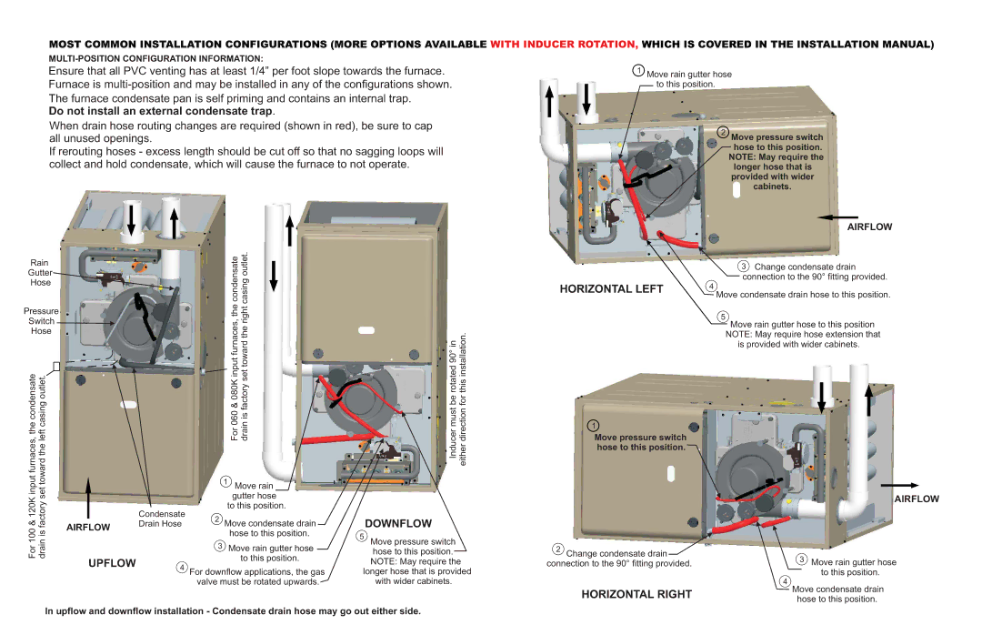
MOST COMMON INSTALLATION CONFIGURATIONS (MORE OPTIONS AVAILABLE WITH INDUCER ROTATION, WHICH IS COVERED IN THE INSTALLATION MANUAL)
Ensure that all PVC venting has at least 1/4” per foot slope towards the furnace. Furnace is
Do not install an external condensate trap.
When drain hose routing changes are required (shown in red), be sure to cap all unused openings.
If rerouting hoses - excess length should be cut off so that no sagging loops will collect and hold condensate, which will cause the furnace to not operate.
1Move rain gutter hose to this position.
2Move pressure switch
hose to this position. NOTE: May require the longer hose that is provided with wider
cabinets.
AIRFLOW
Rain
Gutter
Hose
condensate | outlet. |
3Change condensate drain connection to the 90° fitting provided.
Pressure
Switch ![]()
Hose
condensatefurnaces,& 120Kinputthe | factorytowardcasingoutlet.theleftset |
|
| Condensate |
AIRFLOW | Drain Hose | |||
For 100 | drain is |
| ||
|
|
| ||
UPFLOW | 4 |
|
&080Kinputfurnaces,the | factorysettowardtherightcasing |
For060 | drainis |
1Move rain gutter hose
to this position.
2Move condensate drain hose to this position.
3Move rain gutter hose to this position.
For downflow applications, the gas valve must be rotated upwards.
rotated90°in | thisinstallation. |
Inducermustbe | eitherdirectionfor |
DOWNFLOW
5Move pressure switch
hose to this position. NOTE: May require the longer hose that is provided
with wider cabinets.
HORIZONTAL LEFT
1
Move pressure switch hose to this position.
2Change condensate drain ![]() connection to the 90° fitting provided.
connection to the 90° fitting provided.
HORIZONTAL RIGHT
4
Move condensate drain hose to this position.
5
Move rain gutter hose to this position NOTE: May require hose extension that
is provided with wider cabinets.
AIRFLOW
3Move rain gutter hose to this position.
4
Move condensate drain hose to this position.
In upflow and downflow installation - Condensate drain hose may go out either side.