872678-UIM-C-0213

SECTION VII: SYSTEM CHARGE

The factory charge in the outdoor unit includes enough charge for the unit, a 15 ft. (4.6 m) line set, and the smallest indoor coil match-up. Some indoor coil matches may require additional charge. See tabular data sheet provided in unit literature packet for charge requirements.

Do not leave the system open to the atmosphere.

The “TOTAL SYSTEM CHARGE” must be permanently stamped on the unit data plate.

Total system charge is determined as follows:

1.Determine outdoor unit charge from tabular data sheet.

2.Determine indoor coil adjustment from tabular data sheet.

3.Calculate the line charge using the tabular data sheet if line length is greater than 15 feet (4.6 m).

4.Total system charge = item 1 + item 2 + item 3.

5.Permanently stamp the unit data plate with the total amount of refrigerant in the system.

Use the following charging method whenever additional refrigerant is required for the system charge.

DO NOT attempt to pump “Total System Charge” into outdoor unit for maintenance, service, etc. This may cause damage to the com- pressor and/or other components. the outdoor unit only has enough volume for the factory charge, not the “Total System Charge”.

Refrigerant charging should only be carried out by a qualified air conditioning contractor.

Compressor damage will occur if system is improperly charged. On new system installations, charge system per tabular data sheet for the matched coil and follow guidelines in this instruction.

If a calibrated charging cylinder or accurate weighing device is avail- able, add refrigerant accordingly. Otherwise, model-specific charging charts are provided on the access panel of the unit.

SUPERHEAT CHARGING METHOD -

PISTON INDOOR

1.Set the system running in cooling mode by setting the thermostat at least 6°F below the room temperature and operate system for at least 10 – 15 minutes.

2.Refer to the technical guide for the recommended airflow and ver- ify indoor airflow (it should be about 400 SCFM per ton).

3.Measure and record the outdoor ambient (DB) temperature and the suction pressure at the suction service valve.

4.Using the charging chart located on the unit, find the intersection of the outdoor ambient dry bulb and the suction pressure obtained in step 3. This is the recommended suction tube temperature at the service valve.

5.Measure and record the suction tube temperature at the service valve and compare to the recommended temperature obtained in step 4.

6.Add charge if the measured suction temperature in step 5 is above the recommended value. Remove / recover refrigerant if the mea- sured suction temperature is below the recommended value.

Example: The suction tube temperature listed on the table at the intersection of the outdoor DB and the suction pressure is 63°F. Temperature of the suction tube at the service valve is 68°F. It would be necessary to add refrigerant to drop the suction tube temperature to 63°F.

SUBCOOLING CHARGING METHOD - TXV INDOOR

For cooling operation, unless otherwise specified, the default subcool- ing is 10°F.

1.Set the system running in cooling mode by setting the thermostat at least 6°F below the room temperature and operate system for at least 10 – 15 minutes.

2.Refer to the technical guide for the recommended indoor airflow and verify it is correct (it should be about 400 SCFM per ton).

3.Measure and record the indoor wet bulb (WB) and the outdoor ambient dry bulb (DB) temperature.

4.Using the charging chart located on the unit, find the intersection of the indoor wet bulb and the outdoor dry bulb. This is the recom- mended liquid pressure (and subcooling value).

5.Measure and record the pressure at the liquid valve pressure port and compare to the value obtained in step 4.

6.Add charge if the measured liquid pressure is lower than the rec- ommended value. Remove / recover charge if the measured liquid pressure is above the recommended value.

Example: The liquid pressure listed at the intersection of the indoor WB and the outdoor DB 320 psig. Pressure at the liquid valve is 305 psig. It would be necessary to add refrigerant to increase the liquid pressure to 320 psig.

Condenser subcooling is obtained by calculating the difference of the saturated refrigerant temperature of the pressure measured at the liquid base valve and the liquid tube temperature as measured at the liquid base valve.

Subcooling Temp. (TC) = Saturated Temp. (TS) – Liquid Temp. (T).

IT IS UNLAWFUL TO KNOWINGLY VENT, RELEASE OR DIS- CHARGE REFRIGERANT INTO THE OPEN AIR DURING REPAIR, SERVICE, MAINTENANCE OR THE FINAL DISPOSAL OF THIS UNIT.

6

Johnson Controls Unitary Products

Page 6
Image 6
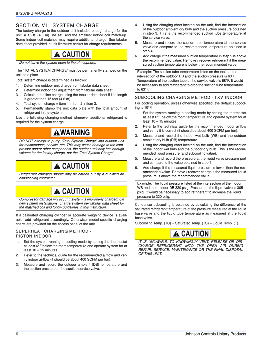
Johnson Controls YCJ(D, TCJ(D, GCGD, F) SERIES Section VII System Charge, Superheat Charging Method Piston Indoor

F) SERIES, 13 & 14.5 SEER - TCG(D, F), GCGD, TCJ(D specifications

Johnson Controls has long been a pioneer in HVAC technology, and their F-Series air conditioning units, specifically the 13 and 14.5 SEER models, have garnered attention for their efficiency and innovative features. The F-Series models TCG(D, F) and TCJ(D, GCGD) stand out in the market, offering a blend of advanced technology, energy efficiency, and user-friendly design.

One of the main features of the TCG and TCJ series is their high Seasonal Energy Efficiency Ratio (SEER), with options of 13 and 14.5 SEER. This high efficiency not only translates to lower energy bills for consumers but also promotes environmental sustainability by reducing carbon footprints. These units are designed to perform optimally in various climates, making them a versatile choice for homeowners and businesses alike.

Incorporating advanced refrigeration technology, the F-Series units utilize scroll compressors that are known for their reliability and efficiency. This type of compressor operates quietly and reduces the chances of breakdown, ensuring longevity and minimal maintenance. Additionally, the variable speed operation allows for better humidity control and comfort, adjusting to the specific cooling needs of the space.

Another key characteristic of Johnson Controls' F-Series is their advanced airflow design. The units are engineered to provide consistent and effective airflow, resulting in even temperature distribution throughout the space. With adjustable louvers, users can easily direct airflow to specific areas, enhancing comfort levels.

The TCG and TCJ models also feature enhanced filtration systems that significantly improve indoor air quality. These systems capture airborne particles and allergens, contributing to a healthier living environment. This focus on air quality is particularly beneficial for families with young children, the elderly, or individuals with respiratory issues.

For ease of use, Johnson Controls has integrated smart technology into their F-Series units. With Wi-Fi connectivity options, users can control their HVAC systems remotely through a smartphone app, allowing for convenient adjustments and energy management. This feature is increasingly important in today’s digital age, where home automation systems are becoming commonplace.

In summary, the Johnson Controls F-Series, particularly the 13 and 14.5 SEER models such as TCG(D, F) and TCJ(D, GCGD), showcase an impressive blend of energy efficiency, advanced technology, and user-centric features. With their reliable performance, superior air quality, and smart technology integration, these air conditioning units represent a solid investment for anyone looking to enhance their indoor comfort while being mindful of energy consumption.