2
Note that the DC voltage switch is continuously variable and that the voltage level labels are approximate.
4.Plug the
5.Connect the VM 3000 to Converter Cable, part number
Note 1: The even numbered ports on the VM 3000 will not work for this applica- tion.
Note 2: The
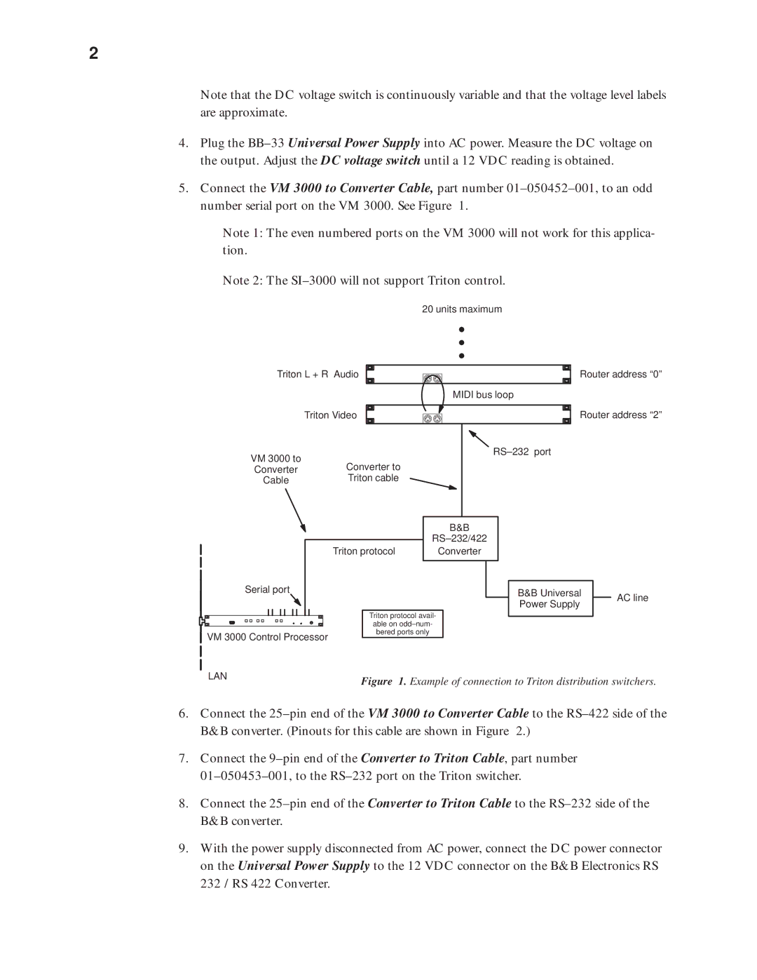
20 units maximum
Triton L + R Audio ![]() Router address “0”
Router address “0”
MIDI bus loop
| Triton Video |
VM 3000 to | Converter to |
Converter | |
Cable | Triton cable |
Router address “2”
RS–232 port
B&B
RS–232/422
Triton protocol | Converter |
Serial port
VM 3000 Control Processor
Triton protocol avail- able on
B&B Universal Power Supply
AC line
LAN | Figure 1. Example of connection to Triton distribution switchers. |
|
6.Connect the
7.Connect the
8.Connect the
9.With the power supply disconnected from AC power, connect the DC power connector on the Universal Power Supply to the 12 VDC connector on the B&B Electronics RS 232 / RS 422 Converter.