Preparation
4 Connecting other devices
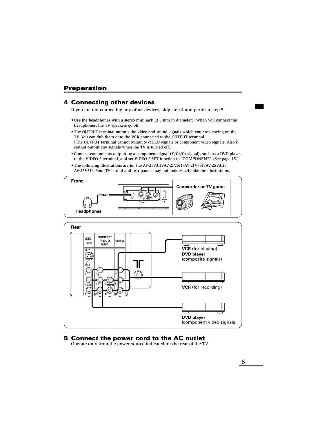
If you are not connecting any other devices, skip step 4 and perform step 5.
•Use the headphones with a stereo mini jack (3.5 mm in diameter). When you connect the headphones, the TV speakers go off.
•The OUTPUT terminal outputs the video and sound signals which you are viewing on the TV. You can dub them onto the VCR connected to the OUTPUT terminal.
(The OUTPUT terminal cannot output
•Connect components outputting a component signal (Y/CB/CR signal), such as a DVD player, to the
•The following illustrations are for the
Front
Headphones
Rear
COMPONENT |
| ||
| OUTPUT | ||
INPUT |
| ||
| INPUT |
| |
|
|
| |
S |
|
|
|
OVER |
|
|
|
V | Y/V |
| V |
L/ MONO | CB | L/ MONO L | |
![]() Camcorder or TV game
Camcorder or TV game
VCR (for playing)
DVD player (composite signals)
VCR (for recording)
R
CR R R
DVD player
(component video signals)
5 Connect the power cord to the AC outlet
Operate only from the power source indicated on the rear of the TV.
5