4
Trim plate Frontrahmen Plaque d’assemblage Sierplaat
7
Sleeve Halterung Manchon Huis
Remonter le panneau de commande.
Rubber cushion Gummipuffer Amortisseur en caoutchouc Rubberdop
9
Attachez la plaque d’assemblage.
8
7 Faire glisser l’appareil dans le manchon jusqu’à ce qu’il soit verrouillé.
Réalisez les connexions électriques.
6
* Après installation correcte du manchon dans le tableau de bord, plier les bonnes pattes pour maintenir fermement le manchon en place, comme montré.
5 Monter le boulon de montage sur l’arrière du corps de l’appareil puis passer l’amortisseur en caoutchouc sur l’extrémité du boulon.
Installer le manchon dans le tableau de bord.
4
FRANÇAIS
• Cet appareil est conçu pour fonctionner sur des sources de courant continu de 12 V à masse
NEGATIVE.
INSTALLATION (MONTAGE DANS LE TABLEAU DE BORD)
• L’illustration suivante est un exemple d’installation typique. Cependant, vous devez faire les ajustements correspondant à votre voiture particulière. Si vous avez des questions ou avez besoin d’information sur des kits d’installation, consulter votre revendeur d’autoradios JVC ou une compagnie d’approvisionnement.
1 Avant le montage: Appuyer sur (déblocage du panneau de commande) pour éventeullement détacher le panneau de commande.
* Lorsque ce panneau de commande sort d’usine, il est rangé dans un étui de transport.
2 Retirer la plaque d’assemblage.
3 Libérer les verrous du manchon et retirer le manchon.
1 Poser l’appareil à la verticale.
Remarque: Lorsque vous mettez l’appareil à la verticale, faire attention de ne pas endommager le fusible situé sur l’arrière.
2 Insérer les 2 poignées entre l’appareil et le manchon comme indiqué pour désengagé les verrous de manchon.
3 Retirer le manchon.
Remarque: S’assurer de garder les poignées pour une utilisation ultérieur, après l’installation de l’appareil.
KS-FX742R
Installation/Connection Manual
Einbau/Anschlußanleitung
Manuel d’installation/raccordement
Handleiding voor installatie/aansluiting
GET0114-003A[E/EX]
| ENGLISH | | | DEUTSCH | | |
| | | | | |
• | This unit is designed to operate on 12 V DC, | • Dieses Gerät ist für einen Betrieb in elektrischen |
| NEGATIVE ground electrical systems. | | Anlagen mit 12 V Gleichstrom und (–) Erdung |
| | | | | ausgelegt. | | |
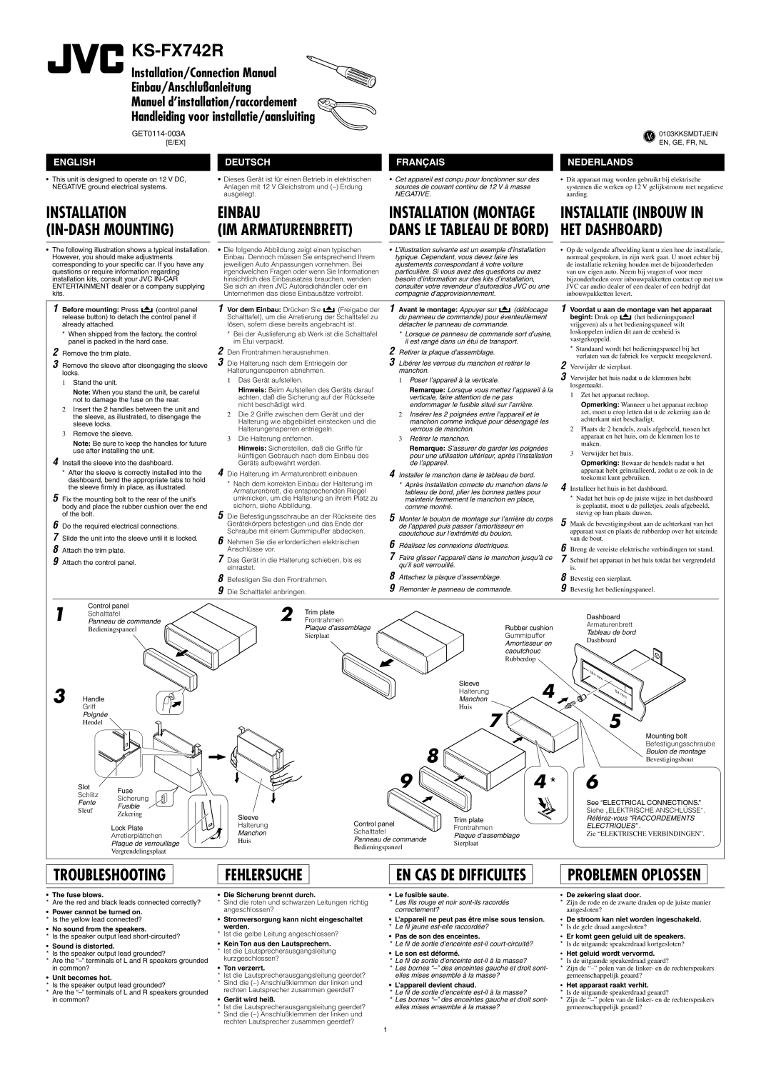
INSTALLATION | | EINBAU | | |
(IN-DASH MOUNTING) | (IM ARMATURENBRETT) |
| | | | |
• | The following illustration shows a typical installation. | • Die folgende Abbildung zeigt einen typischen |
| However, you should make adjustments | | Einbau. Dennoch müssen Sie entsprechend Ihrem |
| corresponding to your specific car. If you have any | | jeweiligen Auto Anpassungen vornehmen. Bei |
| questions or require information regarding | | irgendwelchen Fragen oder wenn Sie Informationen |
| installation kits, consult your JVC IN-CAR | | hinsichtlich des Einbausatzes brauchen, wenden |
| ENTERTAINMENT dealer or a company supplying | | Sie sich an ihren JVC Autoradiohändler oder ein |
| kits. | | | | Unternehmen das diese Einbausätze vertreibt. |
| 1 Before mounting: Press | (control panel | 1 Vor dem Einbau: Drücken Sie | (Freigabe der |
| release button) to detach the control panel if | | Schalttafel), um die Arretierung der Schalttafel zu |
| already attached. | | | lösen, sofern diese bereits angebracht ist. |
| * When shipped from the factory, the control | | * Bei der Auslieferung ab Werk ist die Schalttafel |
| | panel is packed in the hard case. | | im Etui verpackt. | | |
| 2 Remove the trim plate. | | 2 Den Frontrahmen herausnehmen. | |
| 3 Remove the sleeve after disengaging the sleeve | 3 Die Halterung nach dem Entriegeln der |
| locks. | | | Halterungensperren abnehmen. | |
| | | 1 Das Gerät aufstellen. | | |
| 1 Stand the unit. | | | | |
| | | Hinweis: Beim Aufstellen des Geräts darauf |
| | Note: When you stand the unit, be careful | |
| | | achten, daß die Sicherung auf der Rückseite |
| | not to damage the fuse on the rear. | |
| | | nicht beschädigt wird. | |
| 2 Insert the 2 handles between the unit and | | |
| | 2 Die 2 Griffe zwischen dem Gerät und der |
| | the sleeve, as illustrated, to disengage the | |
| | | Halterung wie abgebildet einstecken und die |
| | sleeve locks. | | |
| | | | Halterungensperren entriegeln. | |
| 3 Remove the sleeve. | | | |
| | | 3 Die Halterung entfernen. | |
| | Note: Be sure to keep the handles for future | | |
| | | Hinweis: Sicherstellen, daß die Griffe für |
| | use after installing the unit. | | |
| | | | künftigen Gebrauch nach dem Einbau des |
| 4 Install the sleeve into the dashboard. | |
| | Geräts aufbewahrt werden. | |
| * | After the sleeve is correctly installed into the | 4 Die Halterung im Armaturenbrett einbauen. |
| | dashboard, bend the appropriate tabs to hold | | * Nach dem korrekten Einbau der Halterung im |
| | the sleeve firmly in place, as illustrated. | |
| | | Armaturenbrett, die entsprechenden Riegel |
| 5 Fix the mounting bolt to the rear of the unit’s | |
| | umknicken, um die Halterung an ihrem Platz zu |
| body and place the rubber cushion over the end | | sichern, siehe Abbildung. | |
| of the bolt. | | 5 Die Befestigungsschraube an der Rückseite des |
| 6 Do the required electrical connections. | | Gerätekörpers befestigen und das Ende der |
| 7 Slide the unit into the sleeve until it is locked. | | Schraube mit einem Gummipuffer abdecken. |
| 6 Nehmen Sie die erforderlichen elektrischen |
| 8 Attach the trim plate. | | | Anschlüsse vor. | | |
| 9 Attach the control panel. | | 7 Das Gerät in die Halterung schieben, bis es |
| | | | | einrastet. | | |
| | | | 8 Befestigen Sie den Frontrahmen. | |
| | | | 9 Die Schalttafel anbringen. | |
| 1 | Control panel | | 2 | Trim plate | |
| Schalttafel | | |
| Panneau de commande | Frontrahmen |
| | Bedieningspaneel | | | | Plaque d’assemblage |
| | | | | | Sierplaat | |
V 0103KKSMDTJEIN
J C
EN, GE, FR, NL
NEDERLANDS
•Dit apparaat mag worden gebruikt bij elektrische systemen die werken op 12 V gelijkstroom met negatieve aarding.
INSTALLATIE (INBOUW IN HET DASHBOARD)
•Op de volgende afbeelding kunt u zien hoe de installatie, normaal gesproken, in zijn werk gaat. U moet echter bij de installatie rekening houden met de bijzonderheden van uw eigen auto. Neem bij vragen of voor meer bijzonderheden over inbouwpakketten contact op met uw JVC car audio dealer of een dealer of een bedrijf dat inbouwpakketten levert.
1 Voordat u aan de montage van het apparaat
begint: Druk op  (het bedieningspaneel vrijgeven) als u het bedieningspaneel wilt loskoppelen indien dit aan de eenheid is vastgekoppeld.
*Standaard wordt het bedieningspaneel bij het verlaten van de fabriek los verpackt meegeleverd.
2 Verwijder de sierplaat.
3 Verwijder het huis nadat u de klemmen hebt losgemaakt.
1Zet het apparaat rechtop.
Opmerking: Wanneer u het apparaat rechtop zet, moet u erop letten dat u de zekering aan de achterkant niet beschadigt.
2Plaats de 2 hendels, zoals afgebeeld, tussen het apparaat en het huis, om de klemmen los te maken.
3Verwijder het huis.
Opmerking: Bewaar de hendels nadat u het apparaat hebt geïnstalleerd, zodat u ze ook in de toekomst kunt gebruiken.
4 Installeer het huis in het dashboard.
*Nadat het huis op de juiste wijze in het dashboard is geplaatst, moet u de palletjes, zoals afgebeeld, stevig op hun plaats duwen.
5 Maak de bevestigingsbout aan de achterkant van het apparaat vast en plaats de rubberdop over het uiteinde van de bout.
6 Breng de vereiste elektrische verbindingen tot stand.
7 Schuif het apparaat in het huis totdat het vergrendeld is.
8 Bevestig een sierplaat.
9 Bevestig het bedieningspaneel.
Dashboard
Armaturenbrett
Tableau de bord
Dashboard
3 Handle
Griff
Poignée
Hendel
Slot Fuse
Schlitz Sicherung
Fente Fusible
Sleuf
Zekering
Lock Plate
Arretierplättchen
Plaque de verrouillage
Vergrendelingsplaat
8
| 9 |
Sleeve | Control panel |
Halterung |
Manchon | Schalttafel |
Huis | Panneau de commande |
| Bedieningspaneel |
5
Mounting bolt
Befestigungsschraube
Boulon de montage
Bevestigingsbout
*6
See “ELECTRICAL CONNECTIONS.”
Siehe „ELEKTRISCHE ANSCHLÜSSE“.
Référez-vous “RACCORDEMENTS
ELECTRIQUES” .
Zie “ELEKTRISCHE VERBINDINGEN”.
TROUBLESHOOTING
FEHLERSUCHE
PROBLEMEN OPLOSSEN
•The fuse blows.
* Are the red and black leads connected correctly?
•Power cannot be turned on. * Is the yellow lead connected?
•No sound from the speakers.
* Is the speaker output lead short-circuited?
•Sound is distorted.
*Is the speaker output lead grounded?
*Are the “–” terminals of L and R speakers grounded in common?
•Unit becomes hot.
*Is the speaker output lead grounded?
*Are the “–” terminals of L and R speakers grounded in common?
• Die Sicherung brennt durch.
*Sind die roten und schwarzen Leitungen richtig angeschlossen?
•Stromversorgung kann nicht eingeschaltet werden.
* Ist die gelbe Leitung angeschlossen?
•Kein Ton aus den Lautsprechern. * Ist die Lautsprecherausgangsleitung
kurzgeschlossen?
•Ton verzerrt.
*Ist die Lautsprecherausgangsleitung geerdet?
*Sind die (–) Anschlußklemmen der linken und rechten Lautsprecher zusammen geerdet?
• Gerät wird heiß.
*Ist die Lautsprecherausgangsleitung geerdet?
*Sind die (–) Anschlußklemmen der linken und rechten Lautsprecher zusammen geerdet?
• Le fusible saute.
*Les fils rouge et noir sont-ils racordés correctement?
•L’appareil ne peut pas être mise sous tension. * Le fil jaune est-elle raccordée?
•Pas de son des enceintes.
* Le fil de sortie d’enceinte est-il court-circuité?
• Le son est déformé.
*Le fil de sortie d’enceinte est-il à la masse?
*Les bornes “–” des enceintes gauche et droit sont- elles mises ensemble à la masse?
• L’appareil devient chaud.
*Le fil de sortie d’enceinte est-il à la masse?
*Les bornes “–” des enceintes gauche et droit sont- elles mises ensemble à la masse?
•De zekering slaat door.
*Zijn de rode en de zwarte draden op de juiste manier aangesloten?
•De stroom kan niet worden ingeschakeld. * Is de gele draad aangesloten?
•Er komt geen geluid uit de speakers.
*Is de uitgaande speakerdraad kortgesloten?
•Het geluid wordt vervormd.
*Is de uitgaande speakerdraad geaard?
*Zijn de “–” polen van de linker- en de rechterspeakers gemeenschappelijk geaard?
•Het apparaat raakt verhit.
*Is de uitgaande speakerdraad geaard?
*Zijn de “–” polen van de linker- en de rechterspeakers gemeenschappelijk geaard?