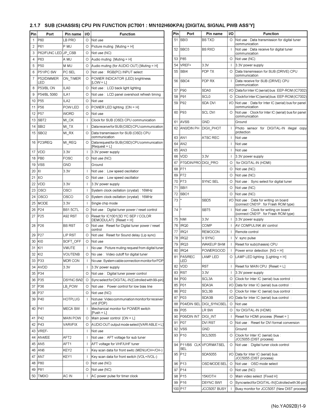
2.1.7 SUB (CHASSIS) CPU PIN FUNCTION (IC7001 : MN102H60KPA) [DIGITAL SIGNAL PWB ASS’Y]

Pin

Port

Pin name

I/O

Function


1

P60

LB PRO

O

Not use


2

P61

P MU

O

Picture muting [Muting = H]


3

P62/FUNC LED

JP_CSB

O

Not use (NC)


4

P63

A MU

O

Audio muting [Muting = H]


5

P50

M MU

O

Audio muting (for AUDIO OUT) [Muting = H]


6

P51/PC SW

PC SEL

O

Not use : RGB(PC) INPUT select


7

P52/DIMMER

ON_TIMER

O

POWER INDICATOR (LED) brightness


LED


[LOW = L]

8

P53/BL ON

ILA0

O

Not use : LCD back light lighting


9

P54/BL 5060

ILA1

O

Not use : LCD panel overshoot refresh timing


10

P55

ILA2

O

Not use


11

P56

POW LED

O

POWER LED lighting [ON = H]


12

P57

WORD

O

Not use


13

SBT2

MI_CK

I

Clock for SUB (OSD) CPU communication


14

SBI2

MI_TX

I

Data receive for SUB (OSD) CPU communication


15

SBO2

MI_RX

O

Data transmission for SUB (OSD) CPU


communication

16

P23/REQ

MI_REQ

O

DatarequestforSUB(OSD)CPUcommunication


[Request = L]

17

VDD

3.3V

I

3.3V power supply


18

PB0

FOSC

O

Not use (NC)


19

VSS

GND


Ground


20

XI

3.3V

I

Not use : Low speed oscillatior


21

XO


O

Not use : Low speed oscillatior


22

VDD

3.3V

I

3.3V power supply


23

OSCI

OSCI

I

System clock osillation (crystal) : 16MHz


24

OSCO

OSCO

O

System clock osillation (crystal) : 16MHz


25

MODE

3.3V

I

Single chip mode


26

P24

BS1.5CTL

O

Not use : Digital tuner power / reset control


27

P25

A92 RST

O

Reset for IC1001(3D YC SEP / COLOR


DEMODULAT) [Reset = H]

28

P26

BS RST

O

Not use: Reset for Digital tuner power / reset


control

29

P27

LIP RST

O

Not use: Reset for Sound delay (Lip sync)


30

KI0

SOFT_OFF

O

Not use


31

KI1

VMUTE

I

No use : Picture muting request from digital tuner


32

KI2

VOUTENB

O

No use : Video cutoff for digital tuner


33

P33

MDR CON

I

No use:Systemcableconnectionmonitor forPDP


34

AVDD

3.3V

I

3.3V power supply


35

P34


O

Not use : Digital tuner power control


36

P35

DSYNC SW2

O

Sync select for DIGITAL-IN [Cotrolled with 99-pin]


37

P36

LB_POW

O

Not use : Power control for low bias line


38

P37


O

Not use (NC)


39

P40

HOTPLUG

I

Notuse:Videocommuniationmonitorfor receiver


unit (PDP)

40

P41

MECA SW

I

Mechanical monitor for POWER switch


[Push = L]

41

P42

MAIN POW

O

Main power control [ON = L]


42

P43

VARI/FIX

O

AUDIO OUT output mode select [VARI ABLE = L]


43

VREF-


I

Not use


44

AN4/EE

AFT2

I

Not use : AFT voltage for sub tuner


45

AN5

AFT1

I

AFT voltage for VHF/UHF tuner


46

AN6

KEY2

I

Key scan data for front switc (MENU/CH+/CH-)


47

AN7

KEY1

I

Key scan data for front switch (VOL+/VOL-)


48

P80


O

Not use (NC)


49

P81


O

Not use (NC)


50

TM0IO

AC IN

I

AC power pulse for timer clock


Pin

Port

Pin name

I/O

Function


51

SBI3

BS TXD

O

Not use : Data transmission for digital tuner


communication


52

SBO3

BS RXD

I

Not use : Data receive for digital tuner


communication


53

P85


O

Not use (NC)


54

VREF+

3.3V

I

3.3V power supply


55

SBI4

PDP TX

O

Data transmission for SUB (DRIVE) CPU


communication


56

SBO4

PDP RX

I

Data receive for SUB (DRIVE) CPU


communication


57

P90

SDA0

I/O

Data for Inter IC (serial) bus : EEP-ROM (IC7002)


58

P91

SCL0

O

ClockforInterIC(serial)bus:EEP-ROM(IC7002)


59

P92

SDA DVI

I/O

Not use : Data for Inter IC (serial) bus for panel


communication


60

P93

SCL DVI

O

Not use : Clock for Inter IC (serial) bus for panel


communication


61

AVSS

GND


Ground


62

AN0/DIN PH

DIGII_PHOT

I

Photo sensor for DIGITAL-IN illegal copy


protection


63

AN1

ATSC REC

I

Not use


64

AN2


I

Not use


65

AN3


I

Not use


66

VDD

3.3V

I

3.3V power supply


67

P70/DINPRO

DIGI_PRO

O

for DIGITAL-IN (HDMI)


68

P71


O

Not use (NC)


69

P72


O

Not use (NC)


70

P73

SYNC SEL

O

Not use : Sync select for digital tuner


71

SBI1


O

Not use (NC)


72

SBO1


O

Not use (NC)


73

*

SBD5

I/O

Not use : Data for writing on board


(connect CN01P : for Frash ROM type)

74

*

SBT5

I

Not use : Clock for writing on board


(connect CN01P : for Frash ROM type)

75

NMI

3.3V

I

3.3V power supply


76

IRQ0

COMP

I

AV COMPULINK áV control


77

IRQ1

REMOCON

I

Remote control


78

IRQ2

V SYNC

I

V. sync pulse


79

IRQ3

WAKEUP SHM

I

Reset for sub(chassis) CPU


80

IRQ4

POWERGOOD

I

Power error detection [NG = H]


81

PA5/REC

LAMP LED

O

LAMP LED lighting [Lighting = H]


LED


82

VDD

RST

I

Reset for MAIN CPU [Reset = L]


83

RST

3.3V

I

3.3V power supply


84

P00

SCL3A

O

Clock for Inter IC (serial) bus control

:


85

P01

SDA3A

I/O

Data for Inter IC (serial) bus control

:


86

P02

SCL3B

O

Clock for Inter IC (serial) bus control

:


87

P03

SDA3B

I/O

Data for Inter IC (serial) bus control

:


88

P04/DIN SEL

DIGI_SYNCSEL

O

Not use


89

P05

LR SW

O

for DIGITAL-IN (HDMI)


90

P06/DIN INT

DIGI_INT

I

Reset for HDMI process [Reset = ]


91

P07

DVI RST

O

Not use : Reset for DVI format conversion


92

VSS

GND


Ground


93

P10

SCL5055

O

Clock for Inter IC (serial) bus :


JCC5055 (DIST process)


94

P11/BS CLK

VFORMATSEL

O

Not use : Digital tuner clock control


SEL


95

P12

SDA5055

I/O

Data for Inter IC (serial) bus :


JCC5055 (DIST process)


96

P13

OSD MODE SEL

O

Not use : OSD mode select


97

P14


O

Not use (NC)


98

P15

15K/OTH

O

Main video select [Fixed H]


99

P16

DSYNC SW1

O

SyncselectforDIGITAL-IN[Cotrolledwith36-pin]


100

P17

JCC5057 BUSY

I

Busy monitor for JCC5057 (New DIST process)


(No.YA092B)1-9

Page 9
Image 9
JVC HD-52Z575 service manual No.YA092B1-9

HD-52Z575 specifications

The JVC HD-52Z575, HD-61Z585, HD-61Z575, and HD-52Z585 are high-definition rear-projection televisions that were part of JVC's impressive line-up in the early 2000s. These models showcased the brand's commitment to providing quality home theater experiences with advanced features and technologies.

One of the standout characteristics of these models is their use of D-ILA (Direct-Drive Image Light Amplifier) technology. D-ILA is a type of liquid crystal display technology similar to LCoS (Liquid Crystal on Silicon) that enhances picture quality by delivering deeper blacks and more vibrant colors. This technology enables the TVs to produce stunning visuals with impressive contrast ratios, making them ideal for various viewing environments.

These models are available in different screen sizes, with HD-52Z575 and HD-52Z585 featuring 52-inch screens, while the HD-61Z585 and HD-61Z575 boast larger 61-inch displays. This range offers versatility for consumers, catering to different room sizes and viewing preferences.

All four models support 1080p resolution, providing an exceptional level of detail and clarity for HD content. This feature makes them suitable for viewing high-definition broadcasts, Blu-ray films, and gaming, allowing users to immerse themselves in their favorite content. The screens also feature a wide viewing angle, ensuring that everyone in the room gets a good view without compromising picture quality.

Connectivity is another strength of these JVC models. Equipped with multiple HDMI ports, component video inputs, and composite inputs, these televisions provide compatibility with a wide range of devices, from gaming consoles to DVD players. Users can easily connect their favorite devices, expanding their entertainment options.

In terms of audio, these JVC TVs are built to complement their visual capabilities, featuring integrated speakers that deliver decent sound quality for everyday use. For those who seek an enhanced audio experience, they offer optical digital audio outputs for external sound systems.

In conclusion, the JVC HD-52Z575, HD-61Z585, HD-61Z575, and HD-52Z585 are notable for their advanced display technologies, high-definition resolutions, and versatile connectivity options. Their D-ILA technology ensures a superior viewing experience, making these rear-projection TVs a compelling choice for any home theater enthusiast looking to enjoy high-quality visuals and sound. Although released in the early 2000s, these models remain a testament to JVC's dedication to innovation and excellence in the television market.