![]()
![]()
![]()
![]() EN 41
EN 41
W E R T Y 
 o
o

 p
p
u
| w Q |
| O |
e I r t y i | U |
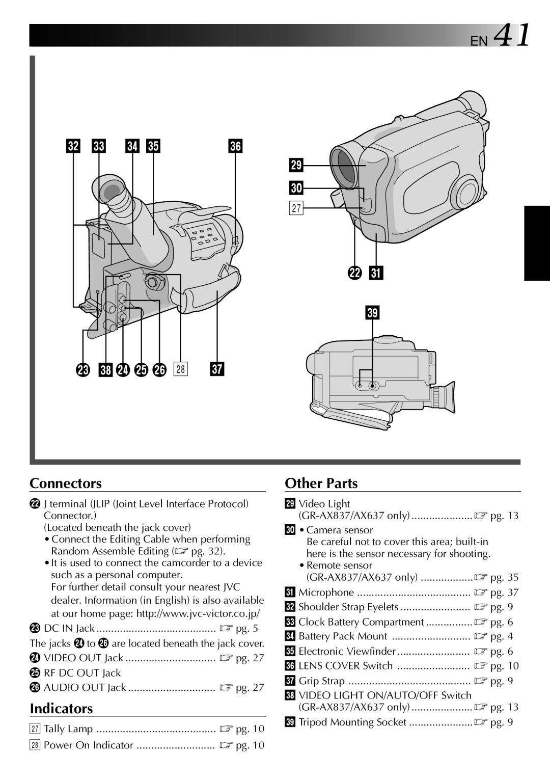
Connectors
wJ terminal (JLIP (Joint Level Interface Protocol) Connector.)
(Located beneath the jack cover)
•Connect the Editing Cable when performing Random Assemble Editing (☞ pg. 32).
•It is used to connect the camcorder to a device such as a personal computer.
For further detail consult your nearest JVC dealer. Information (in English) is also available at our home page:
e DC IN Jack ......................................... ☞ pg. 5
The jacks r to y are located beneath the jack cover.
r VIDEO OUT Jack | ☞ pg. 27 |
t RF DC OUT Jack |
|
y AUDIO OUT Jack | ☞ pg. 27 |
Indicators
u Tally Lamp | ☞ pg. 10 |
i Power On Indicator | ☞ pg. 10 |
Other Parts
o Video Light | ☞ pg. 13 |
p• Camera sensor
Be careful not to cover this area;
• Remote sensor | ☞ pg. 35 |
Q Microphone | ☞ pg. 37 |
W Shoulder Strap Eyelets | ☞ pg. 9 |
E Clock Battery Compartment | ☞ pg. 6 |
R Battery Pack Mount | ☞ pg. 4 |
T Electronic Viewfinder | ☞ pg. 6 |
Y LENS COVER Switch | ☞ pg. 10 |
U Grip Strap | ☞ pg. 9 |
I VIDEO LIGHT ON/AUTO/OFF Switch | ☞ pg. 13 |
O Tripod Mounting Socket | ☞ pg. 9 |