Connections
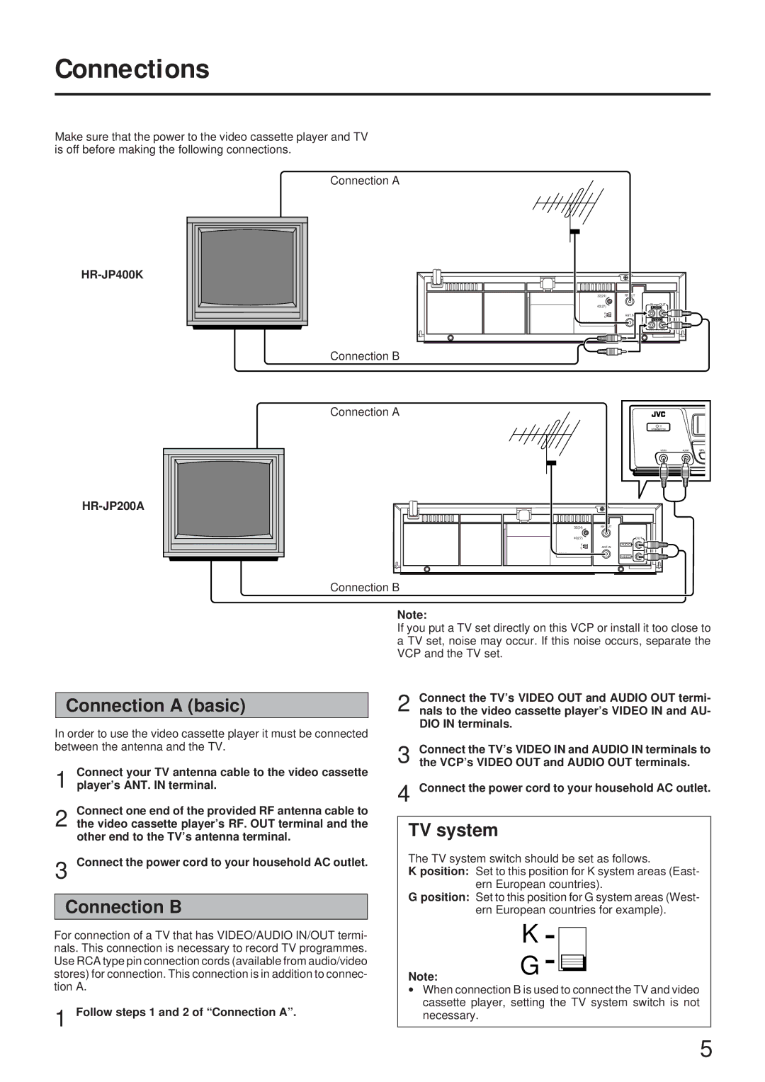
Make sure that the power to the video cassette player and TV is off before making the following connections.
Connection A
Connection B
32(24) | RF OUT |
|
40(27) | IN | OUT |
AUDIO | ||
K | ANT.IN |
|
G |
| |
002 | VIDEO | |
|
| |
Connection A
STANDBY/ON
VIDEOAUDIO
32(24) | RF OUT |
40(27) | OUT |
K | AUDIO |
G | ANT.IN |
002 | VIDEO |
|
Connection B
Connection A (basic)
In order to use the video cassette player it must be connected between the antenna and the TV.
1 Connect your TV antenna cable to the video cassette player’s ANT. IN terminal.
2 Connect one end of the provided RF antenna cable to the video cassette player’s RF. OUT terminal and the other end to the TV’s antenna terminal.
3 Connect the power cord to your household AC outlet.
Connection B
For connection of a TV that has VIDEO/AUDIO IN/OUT termi- nals. This connection is necessary to record TV programmes. Use RCA type pin connection cords (available from audio/video stores) for connection. This connection is in addition to connec- tion A.
1 Follow steps 1 and 2 of “Connection A”.
Note:
If you put a TV set directly on this VCP or install it too close to a TV set, noise may occur. If this noise occurs, separate the VCP and the TV set.
2 Connect the TV’s VIDEO OUT and AUDIO OUT termi- nals to the video cassette player’s VIDEO IN and AU- DIO IN terminals.
3 Connect the TV’s VIDEO IN and AUDIO IN terminals to
the VCP’s VIDEO OUT and AUDIO OUT terminals.
4 Connect the power cord to your household AC outlet.
TV system
The TV system switch should be set as follows.
K position: Set to this position for K system areas (East- ern European countries).
Gposition: Set to this position for G system areas (West- ern European countries for example).
K ![]()
![]()
Note:G
∙When connection B is used to connect the TV and video cassette player, setting the TV system switch is not necessary.
5
