ENGLISH
ELECTRICAL CONNECTIONS
‰∑¬
°“√‡™◊ËÕ¡‚¥¬„™È ‰øøÈ“
ATypical connections / °“√‡™◊ËÕ¡µËÕ·∫∫ª°µ
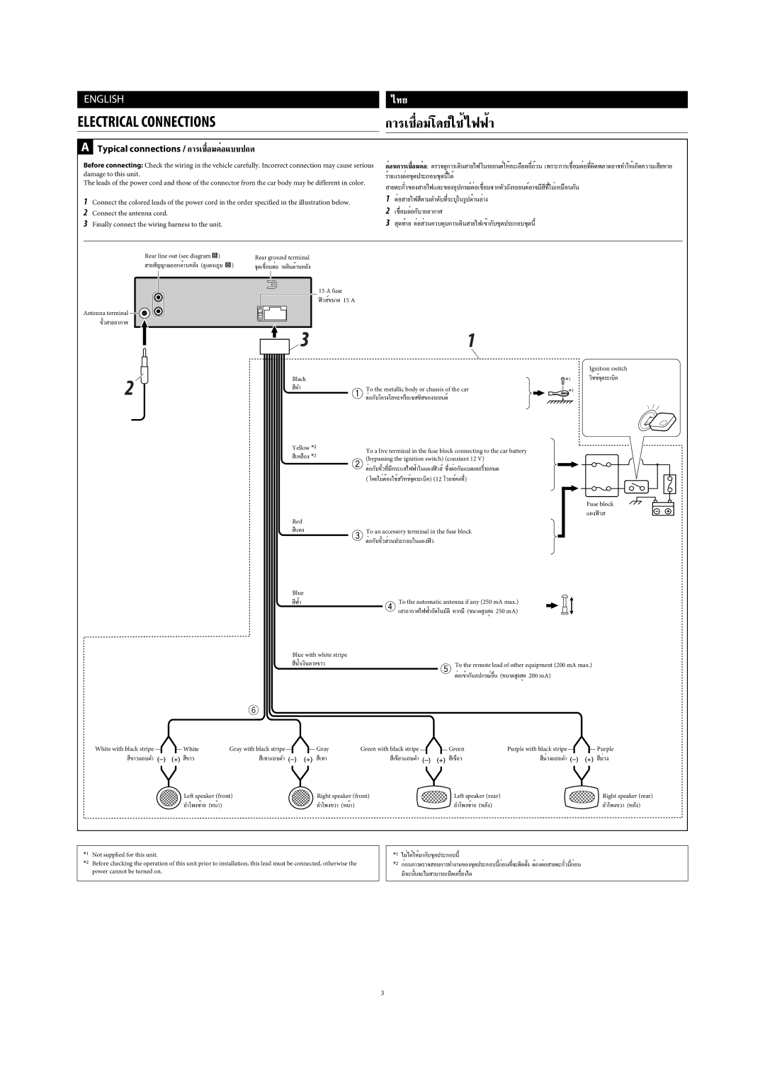
Before connecting: Check the wiring in the vehicle carefully. Incorrect connection may cause serious | °ËÕπ°“√‡™◊ËÕ¡µËÕ: µ√«®¥Ÿ°“√‡¥‘𠓬‰ø | |||||||||||
damage to this unit. |
|
|
|
|
| |||||||
The leads of the power cord and those of the connector from the car body may be different in color. | ||||||||||||
|
|
|
|
|
|
|
|
|
| |||
1 | Connect the colored leads of the power cord in the order specified in the illustration below. | 1 | µËÕ “¬‰ø | |||||||||
2 | Connect the antenna cord. |
|
|
|
| 2 | ||||||
3 | Finally connect the wiring harness to the unit. |
|
|
|
| 3 | ÿ¥∑È“¬ µËÕ Ë«π§«∫§ÿ¡°“√‡¥‘π | |||||
|
|
|
|
|
|
|
|
|
| |||
| Rear line out (see diagram |
| ) |
|
| Rear ground terminal |
|
|
| |||
|
|
|
|
| ||||||||
|
|
|
|
| ||||||||
| “¬ |
| ) | ®ÿ¥‡™◊ËÕ¡µËÕ |
|
|
| |||||
|
|
|
|
| ||||||||
|
|
|
|
|
|
|
|
| 15 A fuse |
|
|
|
|
|
|
|
|
|
|
|
|
|
|
| |
|
|
|
|
|
|
|
|
| øî« Ï¢π“¥15 A |
|
|
|
|
|
|
|
|
|
|
|
|
|
|
|
|
Antenna terminal ![]()
![]()
| Ignition switch | |
Black | ||
’¥” | To the metallic body or chassis of the car | |
| ||
Yellow *2 | To a live terminal in the fuse block connecting to the car battery | |
’‡À≈◊Õß*2 | ||
(bypassing the ignition switch) (constant 12 V) |
( ‚¥¬‰¡ËµÈÕß„™È
Fuse block
·ºßøî«
Red
’·¥ß | To an accessory terminal in the fuse block |
Blue |
|
»’øÈ“ | To the automatic antenna if any (250 mA max.) |
| ‡ |
Blue with white stripe |
|
’πÈ”‡ß‘π≈“¬¢“« | To the remote lead of other equipment (200 mA max.) |
|
|
White with black stripe | White | Gray with black stripe | Gray | Green with black stripe | Green | Purple with black stripe | Purple |
’¢“«·∂∫¥” | ’¢“« | ’‡∑“·∂∫¥” | ’‡∑“ | ’‡¢’¬«·∂∫¥” | ’‡¢’¬« | ’¡Ë«ß·∂∫¥” | ’¡Ë«ß |
| Left speaker (front) | Right speaker (front) | Left speaker (rear) |
| Right speaker (rear) | ||
| ≈”‚æß´È“¬(ÀπÈ“) |
| ≈”‚æߢ«“ (ÀπÈ“) |
|
| ≈”‚æߢ«“ | |
*1 Not supplied for this unit.
*2 Before checking the operation of this unit prior to installation, this lead must be connected, otherwise the power cannot be turned on.
*1
*2 °ËÕπ°“√µ√«®
3
