KD-SX1000R
Installation/Connection Manual
Einbau/Anschlußanleitung
Manuel d’installation/raccordement
ENGLISH
DEUTSCH
•This unit is designed to operate on 12 volts DC, NEGATIVE ground electrical systems.
•Dieses Gerät ist für einen Betrieb in elektrischen Anlagen mit 12 V Gleichstrom und
INSTALLATION | EINBAU |
| (IM ARMATURENBRETT) |
•The following illustration shows a typical installation. However, you should make adjustments corresponding to your specific car. If you have any questions or require information regarding installation kits, consult your JVC
•Die folgende Abbildung zeigt einen typischen Einbau. Dennoch müssen Sie entsprechend Ihrem jeweiligen Auto Anpassungen vornehmen. Bei irgendwelchen Fragen oder wenn Sie Informationen hinsichtlich des Einbausatzes brauchen, wenden Sie sich an ihren JVC Autoradiohändler oder ein Unternehmen das diese Einbausätze vertreibt.
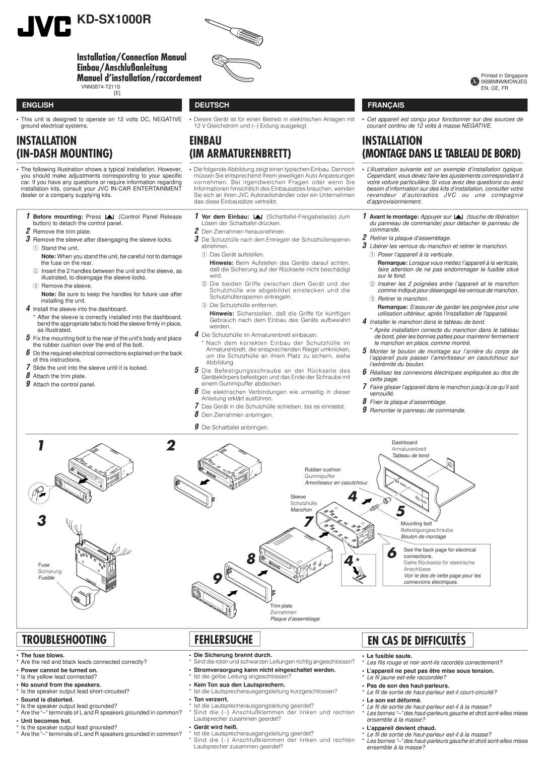
1Before mounting: Press ![]()
![]()
![]() (Control Panel Release button) to detach the control panel.
(Control Panel Release button) to detach the control panel.
2Remove the trim plate.
3Remove the sleeve after disengaging the sleeve locks.
1 Stand the unit.
Note: When you stand the unit, be careful not to damage the fuse on the rear.
2Insert the 2 handles between the unit and the sleeve, as illustrated, to disengage the sleeve locks.
3Remove the sleeve.
Note: Be sure to keep the handles for future use after installing the unit.
4Install the sleeve into the dashboard.
*After the sleeve is correctly installed into the dashboard, bend the appropriate tabs to hold the sleeve firmly in place, as illustrated.
5Fix the mounting bolt to the rear of the unit’s body and place the rubber cushion over the end of the bolt.
6Do the required electrical connections explained on the back of this instructions.
7Slide the unit into the sleeve until it is locked.
8Attach the trim plate.
9Attach the control panel.
1Vor dem Einbau: ![]()
![]()
![]()
2Den Zierrahmen herausnehmen.
3Die Schutzhülle nach dem Entriegeln der Schutzhüllensperren abnehmen.
1 Das Gerät aufstellen.
Hinweis: Beim Aufstellen des Geräts darauf achten, daß die Sicherung auf der Rückseite nicht beschädigt wird.
2Die beiden Griffe zwischen dem Gerät und der Schutzhülle wie abgebildet einstecken und die Schutzhüllensperren entriegeln.
3Die Schutzhülle entfernen.
Hinweis: Sicherstellen, daß die Griffe für künftigen Gebrauch nach dem Einbau des Geräts aufbewahrt werden.
4Die Schutzhülle im Armaturenbrett einbauen.
*Nach dem korrekten Einbau der Schutzhülle im Armaturenbrett, die entsprechenden Riegel umknicken, um die Schutzhülle an ihrem Platz zu sichern, siehe Abbildung.
5Die Befestigungsschraube an der Rückseite des Gerätekörpers befestigen und das Ende der Schraube mit einem Gummipuffer abdecken.
6Die elektrischen Verbindungen wie umseitig in dieser Anleitung erklärt ausführen.
7Das Gerät in die Schutzhülle schieben, bis es einrastet.
8Den Zierrahmen anbringen.
9Die Schalttafel anbringen.
12
Rubber cushion
Gummipuffer
Amortisseur en caoutchouc
Sleeve4
Schutzhülle![]()
Manchon
3 | 7 |
184 | mm |
| |
|
| ||
| 53 | mm | |
5 | |||
| |||
Mounting bolt
Befestigungsschraube
Boulon de montage
Fuse
Sicherung
Fusible
8 | 4 | 6 | See the back page for electrical |
connections. | |||
* | Siehe Rückseite für elektrische | ||
9 |
|
| Anschlüsse. |
|
| Voir le dos de cette page pour les | |
|
| connexions électriques. |
10
Trim plate
Zierrahmen
Plaque d’assemblage
TROUBLESHOOTING
FEHLERSUCHE
EN CAS DE DIFFICULTÉS
•The fuse blows.
* Are the red and black leads connected correctly?
•Power cannot be turned on. * Is the yellow lead connected?
•No sound from the speakers.
* Is the speaker output lead
•Sound is distorted.
*Is the speaker output lead grounded?
*Are the
•Unit becomes hot.
*Is the speaker output lead grounded?
*Are the
• Die Sicherung brennt durch.
* Sind die roten und schwarzen Leitungen richtig angeschlossen?
•Stromversorgung kann nicht eingeschaltet werden. * Ist die gelbe Leitung angeschlossen?
•Kein Ton aus den Lautsprechern.
* Ist die Lautsprecherausgangsleitung kurzgeschlossen?
• Ton verzerrt.
*Ist die Lautsprecherausgangsleitung geerdet?
*Sind die
• Gerät wird heiß.
*Ist die Lautsprecherausgangsleitung geerdet?
*Sind die
• Le fusible saute.
*Les fils rouge et noir
•L’appareil ne peut pas être mise sous tension. * Le fil jaune
•Pas de son des
*Le fil de sortie de
• Le son est déformé.
*Le fil de sortie de
*Les bornes
• L’appareil devient chaud.
*Le fil de sortie de
*Les bornes