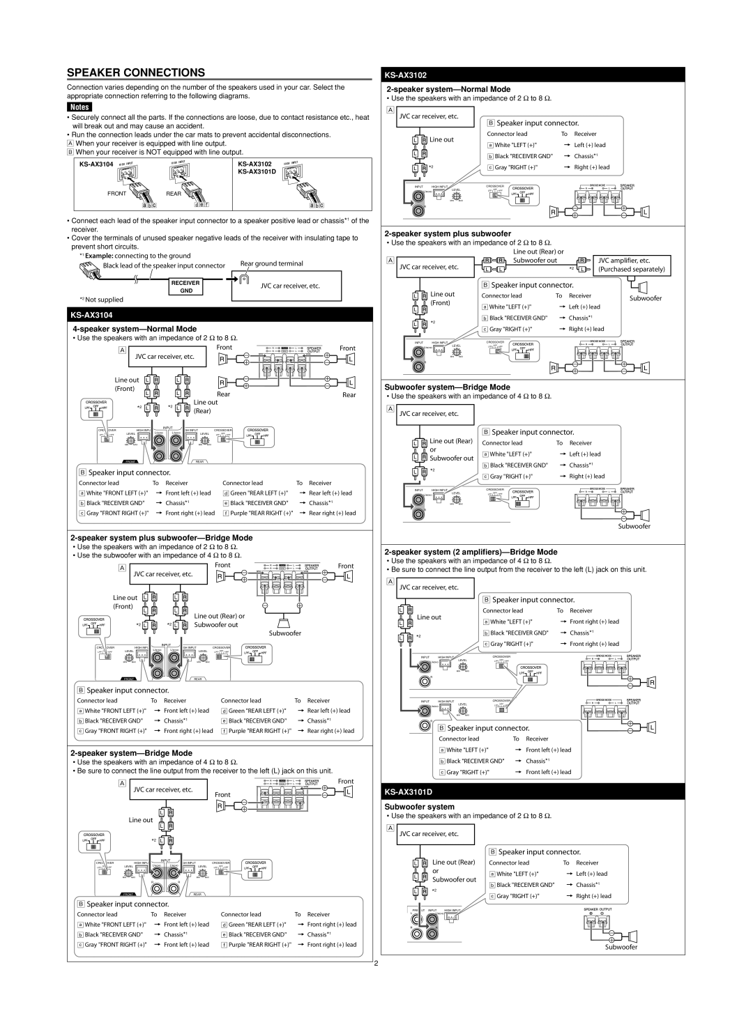
SPEAKER CONNECTIONS
Connection varies depending on the number of the speakers used in your car. Select the appropriate connection referring to the following diagrams.
Notes
•Securely connect all the parts. If the connections are loose, due to contact resistance etc., heat will break out and may cause an accident.
•Run the connection leads under the car mats to prevent accidental disconnections.
ÅWhen your receiver is equipped with line output.
ıWhen your receiver is NOT equipped with line output.
| |
FRONT | REAR |
•Connect each lead of the speaker input connector to a speaker positive lead or chassis*1 of the receiver.
•Cover the terminals of unused speaker negative leads of the receiver with insulating tape to prevent short circuits.
*1 Example: connecting to the ground | Rear ground terminal | |
Black lead of the speaker input connector | ||
|
RECEIVER | JVC car receiver, etc. | |
GND | ||
|
*2 Not supplied
KS-AX3104
4-speaker system—Normal Mode
• Use the speakers with an impedance of 2 Ω to 8 Ω.
Å | Front | REAR | Front |
|
| FRONT |
|
JVC car receiver, etc. |
|
|
|
Line out |
|
|
|
(Front) |
|
|
|
|
|
|
|
| Rear | Rear |
| *2 |
| *2 | Line out |
| |
|
| (Rear) |
|
| ||
|
|
|
|
|
| |
CROSSOVER | HIGH INPUT |
| INPUT | HIGH INPUT | CROSSOVER |
|
L/MONO | L/MONO |
| ||||
LPF OFF HPF | LEVEL | LEVEL | LPF OFF HPF |
| ||
| MIN MAX |
|
| MIN MAX |
|
|
| FRONT |
|
| REAR |
|
|
ıSpeaker input connector.
Connector lead | To Receiver | Connector lead | To Receiver |
aWhite "FRONT LEFT (+)" | = Front left (+) lead | d Green "REAR LEFT (+)" | = Rear left (+) lead |
b Black "RECEIVER GND" | = Chassis*1 | e Black "RECEIVER GND" | = Chassis*1 |
c Gray "FRONT RIGHT (+)" | = Front right (+) lead | f Purple "REAR RIGHT (+)" | = Rear right (+) lead |
2-speaker system plus subwoofer—Bridge Mode
•Use the speakers with an impedance of 2 Ω to 8 Ω.
•Use the subwoofer with an impedance of 4 Ω to 8 Ω.
Å | Front | REAR | Front |
|
| FRONT |
|
JVC car receiver, etc. |
|
|
|
Line out |
|
|
|
(Front) |
|
|
|
|
|
|
| Line out (Rear) or | ||
| *2 |
| *2 | Subwoofer out | ||
|
|
|
|
| Subwoofer | |
CROSSOVER | HIGH INPUT |
| INPUT | HIGH INPUT | CROSSOVER | |
L/MONO | L/MONO | |||||
LPF OFF HPF | LEVEL | LEVEL | LPF OFF HPF | |||
| MIN MAX |
|
| MIN MAX |
| |
|
| R |
|
|
| |
| FRONT |
|
| REAR |
| |
ıSpeaker input connector.
Connector lead | To Receiver | Connector lead | To Receiver |
aWhite "FRONT LEFT (+)" | = Front left (+) lead | d Green "REAR LEFT (+)" | = Rear left (+) lead |
b Black "RECEIVER GND" | = Chassis*1 | e Black "RECEIVER GND" | = Chassis*1 |
c Gray "FRONT RIGHT (+)" | = Front right (+) lead | f Purple "REAR RIGHT (+)" | = Rear right (+) lead |
2-speaker system—Bridge Mode
•Use the speakers with an impedance of 4 Ω to 8 Ω.
•Be sure to connect the line output from the receiver to the left (L) jack on this unit.
Å | REAR | Front |
| FRONT |
|
| JVC car receiver, etc. |
|
| Front |
|
| Line out |
|
*2 ![]()
![]()
![]()
INPUT
CROSSOVER | HIGH INPUT | L/MONO | HIGH INPUT | CROSSOVER | |
LPF OFF HPF | LEVEL | L/MONO | LEVEL | LPF OFF HPF | |
| MIN MAX |
|
| MIN MAX |
|
|
| R | R |
|
|
| FRONT |
|
| REAR |
|
ıSpeaker input connector.
Connector lead | To Receiver | Connector lead | To Receiver |
aWhite "FRONT LEFT (+)" | = Front left (+) lead | d Green "REAR LEFT (+)" | = Front right (+) lead |
b Black "RECEIVER GND" | = Chassis*1 | e Black "RECEIVER GND" | = Chassis*1 |
c Gray "FRONT RIGHT (+)" | = Front left (+) lead | f Purple "REAR RIGHT (+)" | = Front right (+) lead |
2
KS-AX3102
• Use the speakers with an impedance of 2 Ω to 8 Ω.
Å
JVC car receiver, etc.
ıSpeaker input connector.
Line out | Connector lead | To Receiver | |
aWhite "LEFT (+)" | = Left (+) lead | ||
| |||
| b Black "RECEIVER GND" | = Chassis*1 | |
*2 | c Gray "RIGHT (+)" | = Right (+) lead | |
INPUT HIGH INPUT | CROSSOVER |
| |
LEVEL | LPF OFF HPF |
| |
L/MONO |
|
| |
MIN MAX |
|
| |
R |
|
|
|
|
|
|
• Use the speakers with an impedance of 2 Ω to 8 Ω. |
|
| |
| Line out (Rear) or |
|
|
Å | Subwoofer out |
| JVC amplifier, etc. |
JVC car receiver, etc. |
| *2 | (Purchased separately) |
| ı Speaker input connector. |
| |
Line out | Connector lead | To Receiver | Subwoofer |
(Front) |
|
| |
aWhite "LEFT (+)" | = Left (+) lead |
| |
|
| ||
*2 | b Black "RECEIVER GND" | = Chassis*1 |
|
c Gray "RIGHT (+)" | = Right (+) lead |
| |
|
| ||
INPUT HIGH INPUT | CROSSOVER |
|
|
LEVEL | LPF OFF HPF |
|
|
L/MONO |
|
|
|
MIN MAX |
|
|
|
R |
|
|
|
Subwoofer system—Bridge Mode
• Use the speakers with an impedance of 4 Ω to 8 Ω.
ÅJVC car receiver, etc.
ıSpeaker input connector.
Line out (Rear) | Connector lead | To Receiver | |
or | aWhite "LEFT (+)" | = Left (+) lead | |
Subwoofer out | |||
*2 | b Black "RECEIVER GND" | = Chassis*1 | |
c Gray "RIGHT (+)" | = Right (+) lead | ||
| |||
INPUT HIGH INPUT | CROSSOVER |
| |
LEVEL | LPF OFF HPF |
| |
L/MONO |
|
| |
MIN MAX |
|
| |
R |
|
|
Subwoofer
2-speaker system (2 amplifiers)—Bridge Mode
•Use the speakers with an impedance of 4 Ω to 8 Ω.
•Be sure to connect the line output from the receiver to the left (L) jack on this unit.
Å
JVC car receiver, etc.
ı Speaker input connector.
| Connector lead | To Receiver | |||
Line out |
|
| = Front right (+) lead | ||
| aWhite "LEFT (+)" | ||||
*2 | b Black "RECEIVER GND" | = Chassis*1 | |||
c Gray "RIGHT (+)" | = Front right (+) lead | ||||
| |||||
INPUT | HIGH INPUT | CROSSOVER |
| ||
| LEVEL | LPF OFF | HPF |
| |
| L/MONO |
|
|
| |
| MIN MAX |
|
|
| |
| R |
|
|
| |
INPUT | HIGH INPUT | CROSSOVER |
| ||
| LEVEL | LPF OFF | HPF |
| |
| L/MONO |
|
|
| |
| MIN MAX |
|
|
| |
| R |
|
|
| |
| ı Speaker input connector. |
| |||
| Connector lead |
| To Receiver |
| |
| aWhite "LEFT (+)" |
| = Front left (+) lead | ||
| b Black "RECEIVER GND" | = Chassis*1 |
| ||
| c Gray "RIGHT (+)" |
| = Front left (+) lead | ||
KS-AX3101D
Subwoofer system
• Use the speakers with an impedance of 2 Ω to 8 Ω.
Å
JVC car receiver, etc.
ıSpeaker input connector.
| Line out (Rear) | Connector lead | To Receiver |
| or | aWhite "LEFT (+)" | = Left (+) lead |
| Subwoofer out | ||
| b Black "RECEIVER GND" | = Chassis*1 | |
| *2 | ||
| c Gray "RIGHT (+)" | = Right (+) lead | |
|
| ||
PRE | INPUT HIGH INPUT |
|
|
L | L/MONO |
|
|
R | R |
|
|
Subwoofer