Manuals
/
JVC
/
Computer Equipment
/
Computer Drive
JVC
VR-D0U
manual
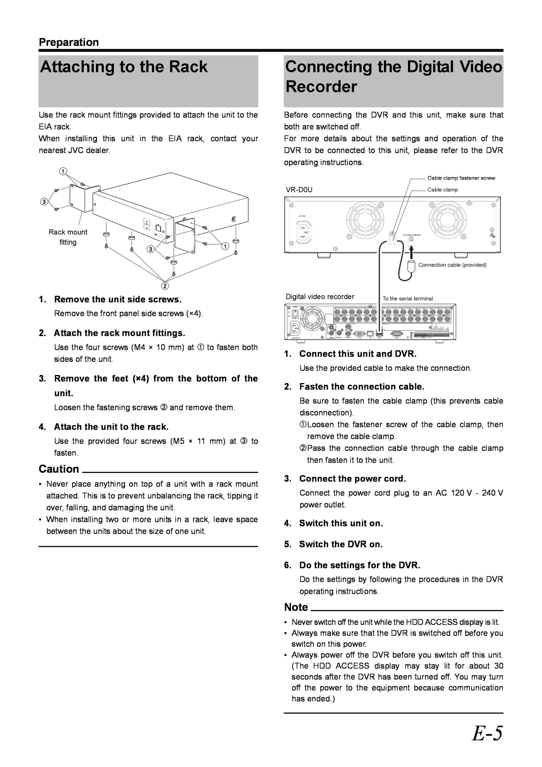
Attaching to the Rack, Connecting the Digital Video Recorder, Preparation
Models:
VR-D0U
1
9
36
36
Download
36 pages
21.74 Kb
6
7
8
9
10
11
12
13
Specification
Safety Precautions
Safety
POWER switch
Page 9
Image 9
Page 8
Page 10
Page 9
Image 9
Page 8
Page 10
Contents
External HDD Unit
Please read the following before getting started
For Customer Use
IMPORTANT SAFEGUARDS
INFORMATION
SAFETY PRECAUTIONS for USA & Canada
AVERTISSEMENT
REMARQUE
POWER SYSTEM Connection to the mains supply
SAFETY PRECAUTIONS
Caution for AC Power Cord
IMPORTANT In the United Kingdom Mains Supply AC 230
Attention This symbol is only valid in the European Union
Information for Users on Disposal of Old Equipment
European Union
Business users
Contents
Main Features
How to Read this Manual
Getting Started
Hard Disk Drive
PRECAUTIONS
5 AC IN Power input terminal
1 POWER switch
Part Names and Functions
Front View
Connecting the Digital Video Recorder
Attaching to the Rack
Preparation
Specifications
Consumable Parts
Others
SPANNUNGSVERSORGUNG
SICHERHEITSVORKEHRUNGEN
WARNUNG
ACHTUNG
Einleitung
HauptmerkmaleInhalt
Vorbereitung
Sonstiges
Festplattenlaufwerk
VORSICHTSHINWEISE
5 Stromeingangsbuchse AC IN
Bezeichnungen und Funktionen der Teile
7 TO RECORDER DVR-Anschlussbuchse
Frontansicht
Anschließen des digitalen
Befestigung am Rack
Videorekorders
Vorbereitung
Technische Daten
Verbrauchsteile
Sonstiges
Attention Ce symbole n’est reconnu que dans l’Union européenne
PRÈCAUTIONS DE SÈCURITÈ
Union européenne
Utilisateurs professionnels
Cet appareil est une Unité HDD
PrincipalesSommaire caractéristiques
Pour commencer
Préparation
Disque dur
PRÉCAUTIONS
Nomenclature et fonctions
1 Interrupteur POWER
Vue de face
Vue de dos
Connexion de l’enregistreur vidéo numérique
Fixation à un bâti
Préparation
Remarque
Caractéristiques techniques
Eléments consommables
Divers
Información para los usuarios sobre la eliminación de equipos usados
PRECAUCIONES DE SEGURIDAD
Unión Europea
Empresas
Contenido
Principales funciones
Introducción
Preparación
Unidad de Disco Duro
PRECAUCIONES
Nombres y funciones de los componentes
1 Interruptor POWER
Vista frontal
Vista trasera
Conexión de la Grabadora
Instalación en el bastidor
de Vídeo Digital
Preparación
Especificaciones
Piezas consumibles
Otros
Unione Europea
PRECAUZIONI PER LA SICUREZZA
Per gli utenti aziendali
Per altre nazioni al di fuori dell’Unione Europea
Indice
Caratteristiche principali
Guida introduttiva
Preparazione
Unità Hard Disk
PRECAUZIONI
Nome e funzione delle parti
1 Interruttore POWER
Lato anteriore
Lato posteriore
Collegamento del
Montaggio in rack
registratore video digitale
Preparazione
Specifiche tecniche
Materiali di consumo
Altro
Page
2006 Victor Company of Japan, Limited
VR-D0U External HDD Unit
Top
Page
Image
Contents