WB-S622U Wall Mount
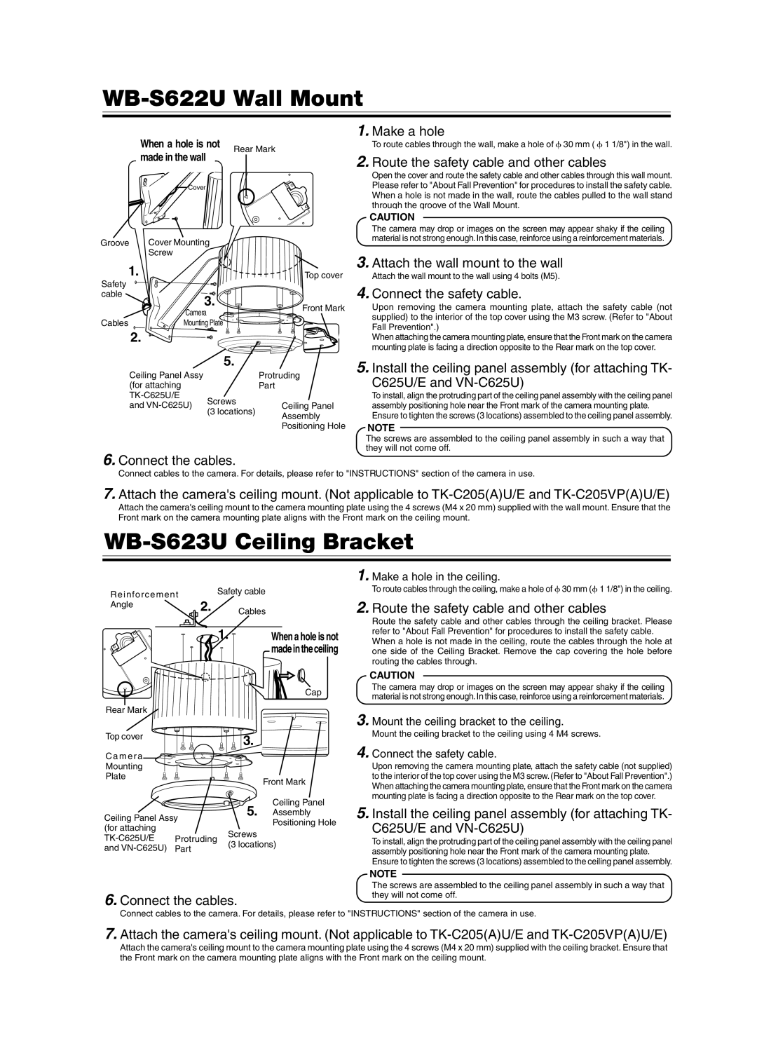
When a hole is not | Rear Mark | |
made in the wall | ||
| ||
Cover |
|
Groove | Cover Mounting |
| |
| Screw |
|
|
1. |
| Top cover | |
Safety |
|
|
|
cable |
| 3. |
|
|
| Front Mark | |
| Camera | ||
|
| ||
Cables | Mounting Plate |
| |
| 2. |
|
|
|
| 5. |
|
| Ceiling Panel Assy |
| Protruding |
| (for attaching |
| Part |
| Screws |
| |
| and | Ceiling Panel | |
| (3 locations) | ||
|
| Assembly | |
|
|
| |
Positioning Hole
6.Connect the cables.
1.Make a hole
To route cables through the wall, make a hole of 30 mm ( 1 1/8") in the wall.
2.Route the safety cable and other cables
Open the cover and route the safety cable and other cables through this wall mount. Please refer to "About Fall Prevention" for procedures to install the safety cable. When a hole is not made in the wall, route the cables pulled to the wall stand through the groove of the Wall Mount.
CAUTION
The camera may drop or images on the screen may appear shaky if the ceiling material is not strong enough. In this case, reinforce using a reinforcement materials.
3.Attach the wall mount to the wall
Attach the wall mount to the wall using 4 bolts (M5).
4.Connect the safety cable.
Upon removing the camera mounting plate, attach the safety cable (not supplied) to the interior of the top cover using the M3 screw. (Refer to "About Fall Prevention".)
When attaching the camera mounting plate, ensure that the Front mark on the camera mounting plate is facing a direction opposite to the Rear mark on the top cover.
5.Install the ceiling panel assembly (for attaching TK-
C625U/E and
To install, align the protruding part of the ceiling panel assembly with the ceiling panel assembly positioning hole near the Front mark of the camera mounting plate. Ensure to tighten the screws (3 locations) assembled to the ceiling panel assembly.
NOTE
The screws are assembled to the ceiling panel assembly in such a way that they will not come off.
Connect cables to the camera. For details, please refer to "INSTRUCTIONS" section of the camera in use.
7.Attach the camera's ceiling mount. (Not applicable to
Attach the camera's ceiling mount to the camera mounting plate using the 4 screws (M4 x 20 mm) supplied with the wall mount. Ensure that the Front mark on the camera mounting plate aligns with the Front mark on the ceiling mount.
WB-S623U Ceiling Bracket
Reinforcement |
| Safety cable |
2. |
| |
Angle | Cables | |
|
1. | When a hole is not |
| madeintheceiling |
| Cap |
Rear Mark
1. Make a hole in the ceiling.
To route cables through the ceiling, make a hole of 30 mm ( 1 1/8") in the ceiling.
2.Route the safety cable and other cables
Route the safety cable and other cables through the ceiling bracket. Please refer to "About Fall Prevention" for procedures to install the safety cable. When a hole is not made in the ceiling, route the cables through the hole at one side of the Ceiling Bracket. Remove the cap covering the hole before routing the cables through.
CAUTION
The camera may drop or images on the screen may appear shaky if the ceiling material is not strong enough. In this case, reinforce using a reinforcement materials.
3. Mount the ceiling bracket to the ceiling.
Top cover
C a m e ra
Mounting
Plate
Ceiling Panel Assy (for attaching
![]()
![]()
![]()
![]() 3.
3.
Front Mark
Ceiling Panel
5. Assembly
Positioning Hole
Screws
(3 locations)
Mount the ceiling bracket to the ceiling using 4 M4 screws.
4. Connect the safety cable.
Upon removing the camera mounting plate, attach the safety cable (not supplied) to the interior of the top cover using the M3 screw. (Refer to "About Fall Prevention".) When attaching the camera mounting plate, ensure that the Front mark on the camera mounting plate is facing a direction opposite to the Rear mark on the top cover.
5.Install the ceiling panel assembly (for attaching TK-
C625U/E and
To install, align the protruding part of the ceiling panel assembly with the ceiling panel assembly positioning hole near the Front mark of the camera mounting plate. Ensure to tighten the screws (3 locations) assembled to the ceiling panel assembly.
6.Connect the cables.
NOTE
The screws are assembled to the ceiling panel assembly in such a way that they will not come off.
Connect cables to the camera. For details, please refer to "INSTRUCTIONS" section of the camera in use.
7.Attach the camera's ceiling mount. (Not applicable to
Attach the camera's ceiling mount to the camera mounting plate using the 4 screws (M4 x 20 mm) supplied with the ceiling bracket. Ensure that the Front mark on the camera mounting plate aligns with the Front mark on the ceiling mount.