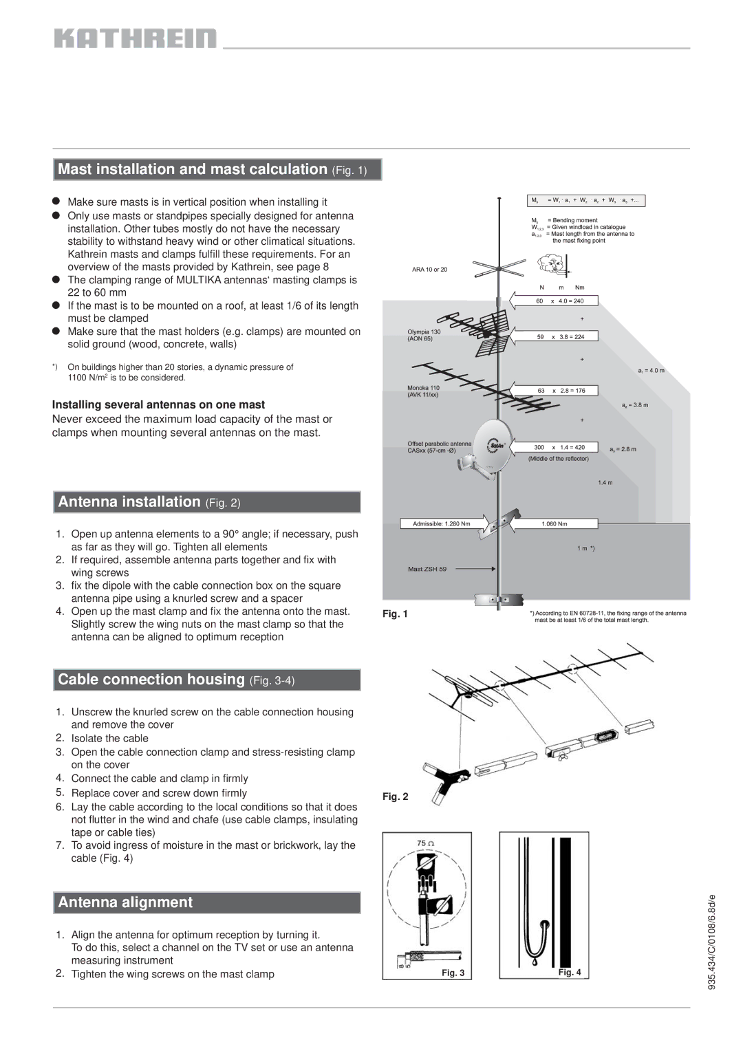
AV 09 211453, AV 12 211473, AV 11 211463, AV 06 211450 specifications
Kathrein, a leader in antenna technology, offers a range of robust and innovative antennas designed for various broadcast applications. Among their prominent products are the AV 11 211463, AV 12 211473, AV 09 211453, and AV 06 211450 models. Each of these antennas comes with features tailored to meet the demands of modern communication systems.The AV 11 211463 is engineered for excellent performance in both UHF and VHF bands. This antenna is designed to ensure maximum signal reception while minimizing interference. It exhibits a high gain, making it ideal for long-distance reception and is constructed with durable materials to withstand harsh weather conditions. Its compact design allows for easy installation in various environments, from residential rooftops to commercial settings.
In contrast, the AV 12 211473 offers enhanced performance with its advanced multi-band functionality. This antenna supports various communication protocols, making it suitable for both television and radio signals. Its innovative design incorporates advanced filtering technology, ensuring clear signal reception and reducing noise. Additionally, the AV 12 benefits from a lightweight construction, facilitating straightforward setup and mounting.
The AV 09 211453 is particularly distinguished for its exceptional directional capabilities. This antenna features a highly focused radiation pattern, which enhances signal strength from specific directions while rejecting unwanted signals from others. It's an optimum choice for applications that require precise signal targeting, such as in densely populated areas. Furthermore, the robust build quality ensures long-term reliability in various environmental conditions.
Lastly, the AV 06 211450 is designed for extensive coverage in urban landscapes. It is optimized for low-band frequencies while maintaining excellent gain, making it ideal for applications in areas with complex signal propagation challenges. This antenna employs cutting-edge technology to improve overall efficiency, ensuring that users receive high-quality signals even in less-than-ideal conditions.
Together, these Kathrein antenna models provide versatile solutions for both commercial and residential applications. Their blend of high gain, durability, and special features makes them highly sought after in the telecommunications industry. Whether for broadcasting, telecommunications, or hybrid applications, each model represents Kathrein's commitment to delivering quality and innovation. Thus, users can rely on these antennas to enhance their signal reception experience significantly.

