ATTACHING WHEELS WITH DEPRESSED CENTERS
![]()
![]() WARNING Always check the tool warning label for the recommend- ed speed rating on accessories. Never run a wheel or brush over the rated speed. Accessories exceeding the recommended speed may fly apart and cause serious personal injury.
WARNING Always check the tool warning label for the recommend- ed speed rating on accessories. Never run a wheel or brush over the rated speed. Accessories exceeding the recommended speed may fly apart and cause serious personal injury.
Hubbed wheels do not require mounting flanges.
ATTACHING WIRE BRUSHES
Wire cup brushes, not included, can be screwed directly on the spindle. No flanges are necessary.
EDGE GRINDING
![]()
![]() WARNING Do not use edge grinding wheels for
WARNING Do not use edge grinding wheels for
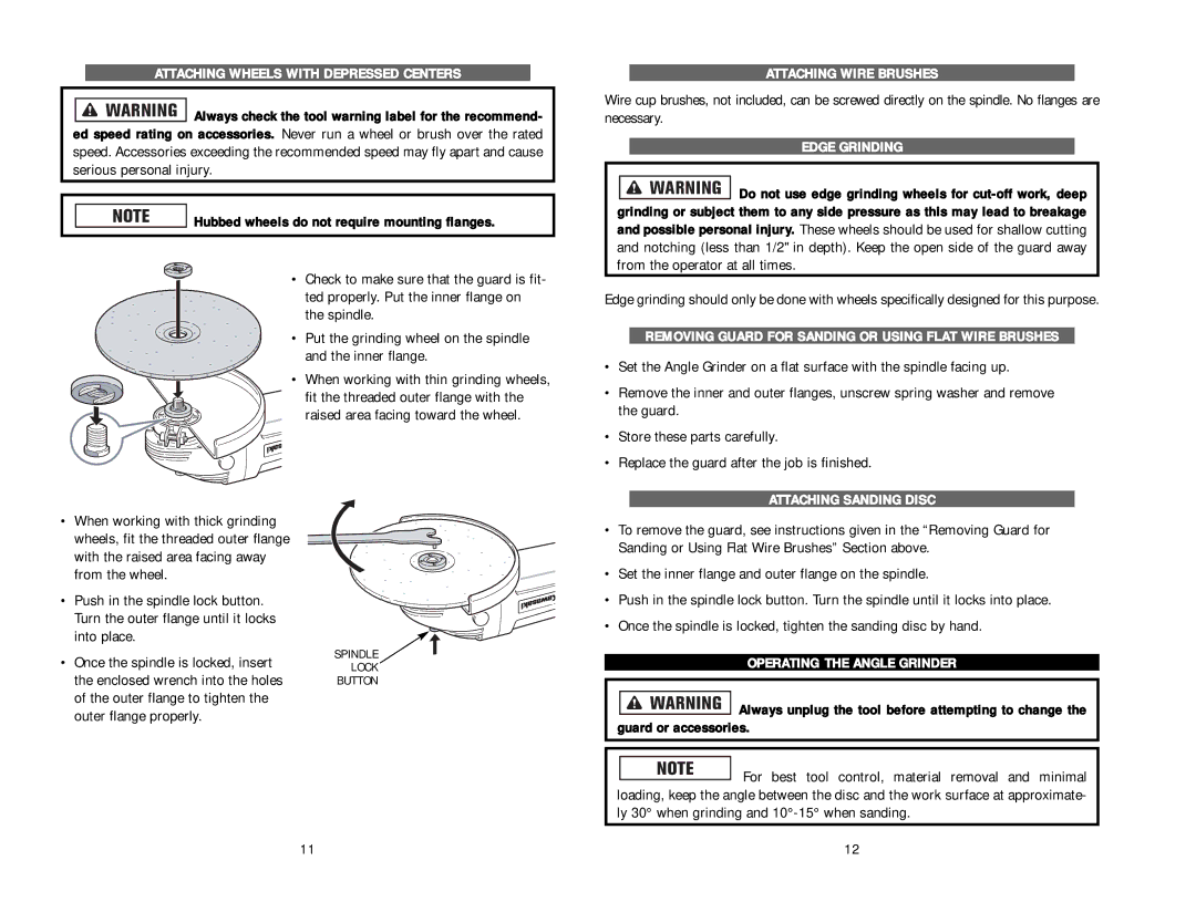
•When working with thick grinding wheels, fit the threaded outer flange with the raised area facing away from the wheel.
•Push in the spindle lock button. Turn the outer flange until it locks into place.
•Once the spindle is locked, insert the enclosed wrench into the holes of the outer flange to tighten the outer flange properly.
•Check to make sure that the guard is fit- ted properly. Put the inner flange on the spindle.
•Put the grinding wheel on the spindle and the inner flange.
•When working with thin grinding wheels, fit the threaded outer flange with the raised area facing toward the wheel.
SPINDLE
LOCK
BUTTON
Edge grinding should only be done with wheels specifically designed for this purpose.
REMOVING GUARD FOR SANDING OR USING FLAT WIRE BRUSHES
•Set the Angle Grinder on a flat surface with the spindle facing up.
•Remove the inner and outer flanges, unscrew spring washer and remove the guard.
•Store these parts carefully.
•Replace the guard after the job is finished.
ATTACHING SANDING DISC
•To remove the guard, see instructions given in the “Removing Guard for Sanding or Using Flat Wire Brushes” Section above.
•Set the inner flange and outer flange on the spindle.
•Push in the spindle lock button. Turn the spindle until it locks into place.
•Once the spindle is locked, tighten the sanding disc by hand.
OPERATING THE ANGLE GRINDER
![]()
![]()
![]()
![]()
![]()
![]()
![]() Always unplug the tool before attempting to change the guard or accessories.
Always unplug the tool before attempting to change the guard or accessories.
![]() For best tool control, material removal and minimal loading, keep the angle between the disc and the work surface at approximate- ly 30° when grinding and
For best tool control, material removal and minimal loading, keep the angle between the disc and the work surface at approximate- ly 30° when grinding and
11 | 12 |