Manuals
/
Kelvinator
/
Kitchen Appliance
/
Refrigerator
Kelvinator
KCBM23F, KCBM72R, KCBM48R, KCBM48F, KCBM23R
warranty
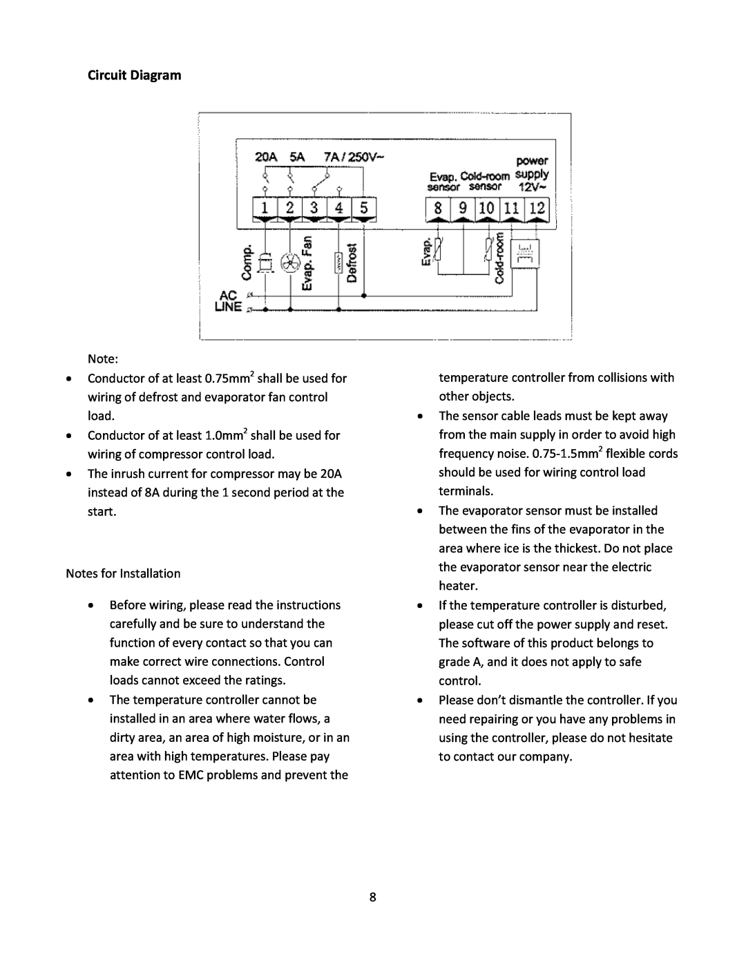
Circuit Diagram
Models:
KCBM23R
KCBM23F
KCBM48F
KCBM48R
KCBM72R
1
8
11
11
Download
11 pages
33.82 Kb
4
5
6
7
8
9
10
11
Troubleshooting
Specifications
Install
Circuit Diagram
Maintenance
Door Problems
Safety
Page 8
Image 8
Page 7
Page 9
Page 8
Image 8
Page 7
Page 9
Contents
TABLE OF CONTENTS
KELVINATOR
C O M M E R C I A L
COMMERCIAL FREEZER/REFRIGERATOR
SAFETY / WARNING
Product Registration
UNPLUG CORD
READ AND SAVE THESE INSTRUCTIONS 242230200 January
INSTALLATION
IMPORTANT!!! PLEASE READ BEFORE INSTALLATION
PROHIBTION
CABINET LOCATION GUIDELINES
Routine Maintenance
Cleaning the Interior
Cleaning the Exterior
Thermostat Setting
Energy Conservation Measures
Periods of Non‐use and Moving Tips
Long Periods of Non‐use
Moving
Feature of Function
Specification
Indicator
Parameter Setup
Parameter details
Circuit Diagram
TROUBLESHOOTING
PROBLEM
GUIDE
CAUSE
DOOR PROBLEMS
LIGHTING PROBLEMS
WATER / MOISTURE / FROST INSIDE APPLIANCE
ODOR IN APPLIANCE
Top
Page
Image
Contents