3, Examine the leveling legs. Find the diamond marking.
4.Screw the legs into the leg holes by hand. Use a wrench to
finish turning the legs until the diamond marking is no longer visible.
5.Place a carton corner post from dryer packaging under each of the 2 dryer back corners. Stand the dryer up. Slide the dryer on the corner posts until it is close to its final location. Leave enough room to connect the exhaust vent.
1.Using a 4" (10.2 cm) clamp, connect vent to exhaust outlet in dryer. If connecting to existing vent, make sure the vent is clean. The dryer vent must fit over the dryer exhaust outlet and inside the exhaust hood. Make sure the vent is secured
to exhaust hood with a 4" (10.2 cm) clamp.
2.Move dryer into its final position. Do not crush or kink vent.
3.(On gas models) Check to be sure there are no kinks in the flexible gas line.
4.Once the exhaust vent connection is made, remove the corner posts and cardboard.
Check the levelness of the dryer. Check levelness first side to side, then front to back.
If the dryer is not level, prop up the dryer using a wood block. Use a wrench to adjust the legs up or down and check again for levelness.
You can change your door swing from a
Remove the door
1.Place a towel or soft cloth on top of the dryer or work space to protect the surface.
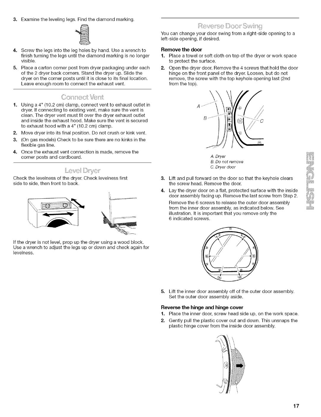
2.Open the dryer door. Remove the 4 screws that hold the door hinge on the front panel of the dryer. Loosen, but do not remove, the screw with the top keyhole opening last (2nd from the top).
A.Dryer
B. Do not remove
C. Dryer door
3, Lift and pull forward on the door so that the keyhole clears the screw head. Remove the door.
4.Lay the dryer door on a flat, protected surface with the inside door assembly facing up. Remove the last screw from Step 2.
Remove the 6 screws to release the outer door assembly from the inner door assembly, as indicated below. See
illustration. It is important that you remove only the 6 indicated screws.
5.Lift the inner door assembly off of the outer door assembly. Set the outer door assembly aside.
Reverse the hinge and hinge cover
1.Place the inner door, screw head side up, on the work space.
2.Gently pull the plastic cover out and down. This unsnaps the plastic hinge cover from the inside door assembly.
17