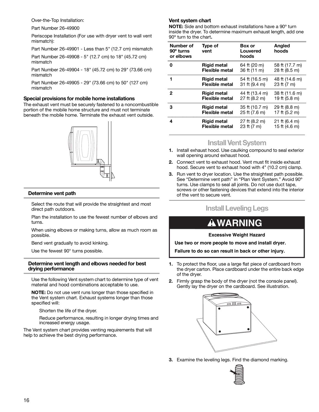
8789, 110.8787 specifications
The Kenmore 110.8787 and 110.8789 are prominent models in the Kenmore washing machine lineup, designed to provide efficiency, durability, and advanced cleaning performance. These machines are known for their stylish design and user-friendly features that cater to various laundry needs.One of the standout characteristics of the Kenmore 110.8787 and 110.8789 is their capacity. With a sizable drum, these washers can accommodate larger loads, making them ideal for families or individuals who frequently wash bulky items like bedding and towels. This larger capacity not only saves time by allowing users to wash more items per load but also promotes better water and energy efficiency.
These machines feature a range of wash cycles designed to handle different fabric types and soil levels. With options such as normal, delicate, heavy-duty, and quick wash, users can customize their laundry experience based on their needs. The intuitive control panel simplifies the process, ensuring that selecting the appropriate cycle is straightforward.
Another significant technological advancement in the Kenmore 110.8787 and 110.8789 is their advanced agitation system. These washers utilize a combination of traditional agitator motion and modern washing technologies, which provide optimal cleaning performance while being gentle on clothes. The machines also incorporate smart sensors that adjust water levels and wash times according to the load size, ensuring resource efficiency.
Energy efficiency is a key selling point for both models, which are designed to consume less water and electricity compared to older washing machines. With ENERGY STAR certifications, users can expect lower utility bills without compromising on performance. The durable construction of the Kenmore 110.8787 and 110.8789 also means that these machines are built to last, featuring high-quality components that withstand regular use.
In addition to performance and efficiency, convenience features such as delay start, end-of-cycle signal, and lint filters make these washers very user-friendly. The sleek design fits well in any laundry room environment, enhancing aesthetics while providing top-notch functionality.
In summary, the Kenmore 110.8787 and 110.8789 washing machines stand out for their impressive capacity, multiple wash cycles, energy efficiency, and thoughtful design. Whether tackling everyday laundry or dealing with particular items, these machines offer a reliable and effective solution for all household washing needs.