11
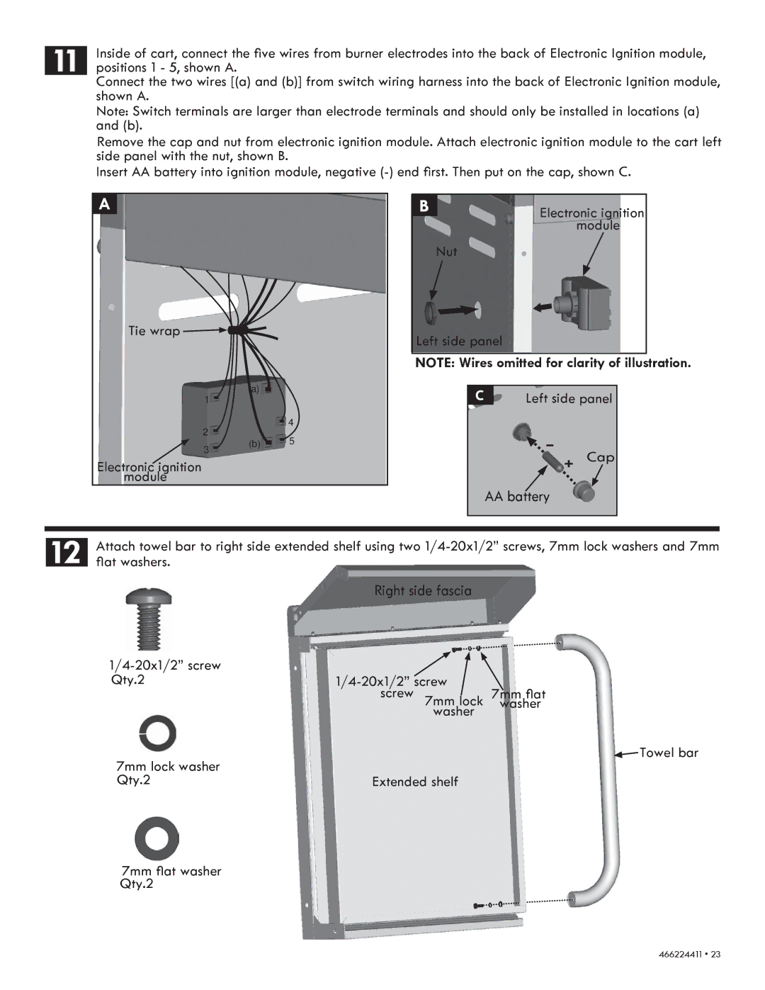
Inside of cart, connect the five wires from burner electrodes into the back of Electronic Ignition module, positions 1 - 5, shown A.
Connect the two wires [(a) and (b)] from switch wiring harness into the back of Electronic Ignition module, shown A.
Note: Switch terminals are larger than electrode terminals and should only be installed in locations (a) and (b).
Remove the cap and nut from electronic ignition module. Attach electronic ignition module to the cart left side panel with the nut, shown B.
Insert AA battery into ignition module, negative
A
Tie wrap 
(a)
1 |
4 |
2 |
B | Electronic ignition |
| |
| module |
| Nut |
Left side panel
NOTE: Wires omitted for clarity of illustration.
C | Left side panel | |
3 | (b) | 5 |
|
|
Electronic ignition module
-
AA battery
+ Cap
12 | Attach towel bar to right side extended shelf using two |
flat washers. |
Right side fascia
Qty.21/4-20x1/2” screw
screw 7mm lock 7mm flat
washer washer
7mm lock washer |
|
| Towel bar |
|
| ||
|
|
| |
Qty.2 | Extended shelf | ||
7mm flat washer Qty.2
466224411 • 23