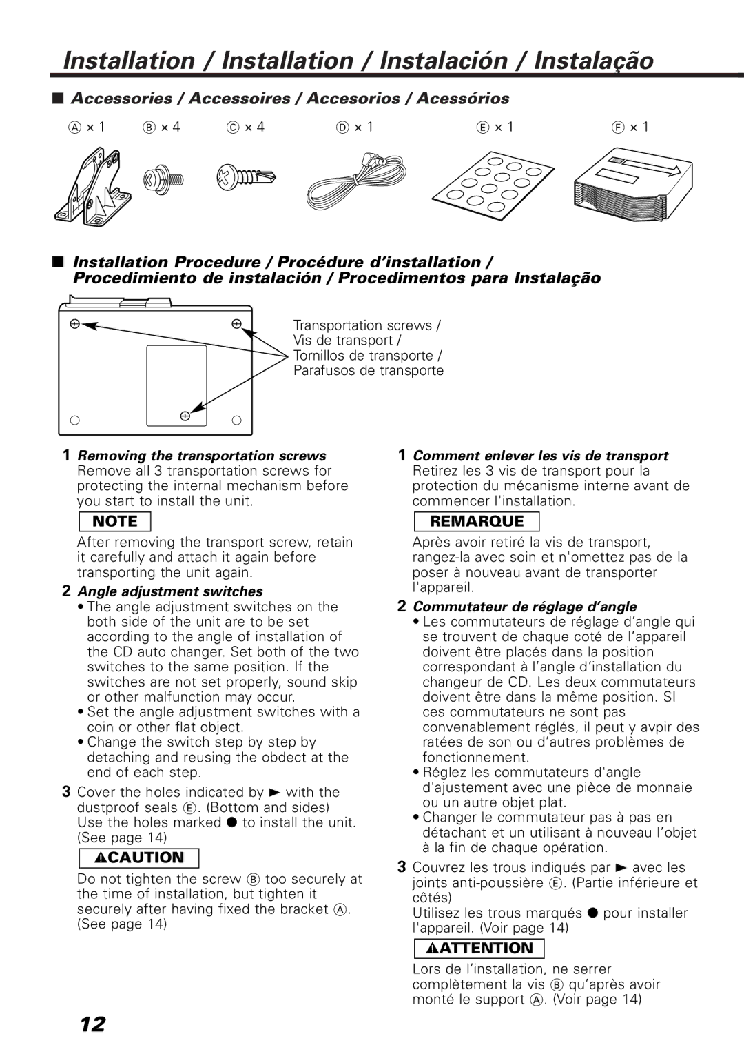
KDC-C467, KDC-C667, KDC-C717 specifications
The Kenwood KDC series of car CD receivers, specifically the KDC-C717, KDC-C667, and KDC-C467, showcases an impressive range of features tailored for audio enthusiasts. These models blend modern technology with user-friendly interfaces, providing an enhanced listening experience on the road.Starting with the Kenwood KDC-C717, this receiver is renowned for its superior audio quality and versatile connectivity options. It supports various audio formats, including MP3, WMA, and WAV, allowing users to enjoy their favorite tracks without compromise. The KDC-C717 comes equipped with a built-in MOSFET amplifier that delivers powerful and clear sound, ensuring every note is crisp and balanced. Additionally, it features a 3-band equalizer, enabling users to fine-tune their audio settings according to their preferences.
Next up is the Kenwood KDC-C667, which caters to the needs of smartphone users with its seamless Bluetooth connectivity. This model allows for hands-free calling and audio streaming, making it easier than ever to enjoy music while keeping your hands on the wheel. The KDC-C667 also includes a USB port, facilitating direct connection to devices for charging and playback. Its adjustable display and customizable color options allow users to personalize their listening experience further.
Lastly, the Kenwood KDC-C467 stands out with its affordability and essential features, making it an excellent choice for budget-conscious consumers. This model retains the quality sound performance that Kenwood is known for while offering a straightforward, easy-to-navigate interface. The KDC-C467 supports AM/FM radio, CD playback, and USB input, making it versatile enough for various media sources. The built-in Bluetooth technology also allows for wireless audio streaming and hands-free calling, ensuring safety and convenience while driving.
Each model in the KDC series is designed with user convenience in mind. They all include features such as remote control compatibility and adjustable display angles for optimal visibility. The innovative technologies employed in these receivers, such as Digital Signal Processing (DSP), enhance the overall audio output, ensuring users enjoy rich and immersive sound.
In conclusion, the Kenwood KDC-C717, KDC-C667, and KDC-C467 provide a range of features that cater to different needs and preferences. Whether you prioritize high-end audio quality, smartphone integration, or budget-friendly options, there's a model in the KDC lineup to suit your demands, making them suitable choices for anyone looking to enhance their car audio experience.

