HF/50MHz TRANSCEIVER | Main receiver |
The newly developed
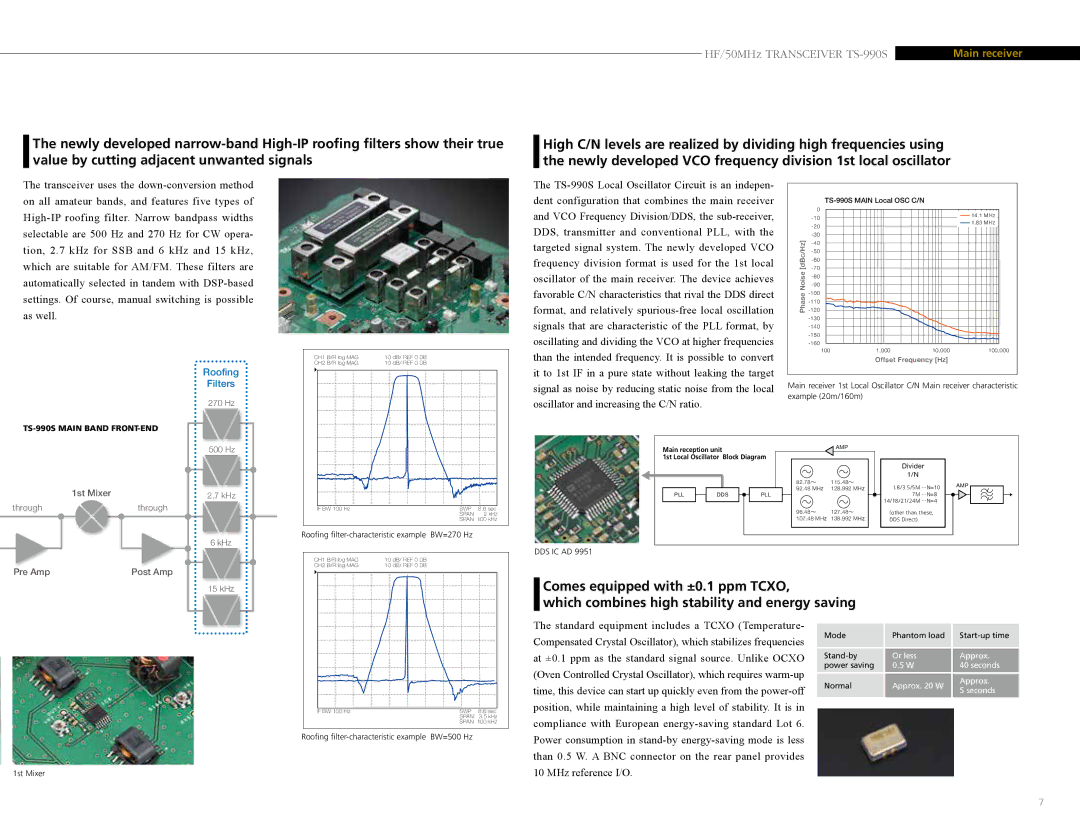
High C/N levels are realized by dividing high frequencies using the newly developed VCO frequency division 1st local oscillator
The transceiver uses the
The
| 0 | 14.1 MHz |
| ||
| 1.83 MHz | |
| ||
|
| |
|
| |
[dBc/Hz] |
| |
| ||
| ||
| ||
Noise |
| |
| ||
| ||
Phase |
| |
| ||
| ||
|
| |
|
| |
|
| |
|
|
Roofing |
Filters |
270 Hz |
CH1 B/R log MAG | 10 dB/ REF 0 DB |
CH2 B/R log MAG | 10 dB/ REF 0 DB |
than the intended frequency. It is possible to convert it to 1st IF in a pure state without leaking the target signal as noise by reducing static noise from the local oscillator and increasing the C/N ratio.
100 | 1,000 | 10,000 | 100,000 |
Offset Frequency [Hz]
Main receiver 1st Local Oscillator C/N Main receiver characteristic example (20m/160m)
|
|
|
|
|
|
| 500 Hz |
| |
| 1st Mixer |
|
|
|
|
|
|
| |
|
|
|
| 2.7 kHz |
| ||||
through | through |
| |||||||
|
|
|
|
|
|
|
|
|
|
|
|
|
|
|
|
| 6 kHz |
| |
|
|
|
|
|
| ||||
Pre Amp | Post Amp |
| |||||||
|
|
|
|
|
|
| 15 kHz |
| |
IF BW 100 Hz | SWP | 8.6 sec |
|
| SPAN | 2 kHz | |
| SPAN 100 kHz | ||
Roofing filter-characteristic example BW=270 Hz
CH1 B/R log MAG | 10 dB/ REF 0 DB |
CH2 B/R log MAG | 10 dB/ REF 0 DB |
Main reception unit |
|
| AMP |
|
|
| |
|
|
|
|
|
| ||
1st Local Oscillator | Block Diagram |
|
|
|
| ||
|
|
|
|
| Divider |
| |
|
|
|
|
| 1/N |
|
|
|
|
| 82.78~ | 115.48~ | 1.8/3.5/5M | ...N=10 | AMP |
|
|
| 92.48 MHz | 128.992 MHz | |||
PLL | DDS | PLL |
| 7M | ...N=8 |
| |
|
|
|
|
| 14/18/21/24M | ...N=4 |
|
|
|
| 96.48~ | 127.48~ | (other than these, |
| |
|
|
| 107.48 MHz | 138.992 MHz | DDS Direct) |
|
|
DDS IC AD 9951
Comes equipped with ±0.1 ppm TCXO,
which combines high stability and energy saving
IF BW 100 Hz | SWP | 8.6 sec |
|
| SPAN | 3.5 kHz | |
| SPAN 100 kHz | ||
Roofing
The standard equipment includes a TCXO (Temperature- Compensated Crystal Oscillator), which stabilizes frequencies at ±0.1 ppm as the standard signal source. Unlike OCXO (Oven Controlled Crystal Oscillator), which requires
Mode | Phantom load | ||
Or less | Approx. | ||
power saving | 0.5 W | 40 seconds | |
Normal | Approx. 20 W | Approx. | |
5 seconds | |||
|
|
1st Mixer
10 MHz reference I/O.
7