
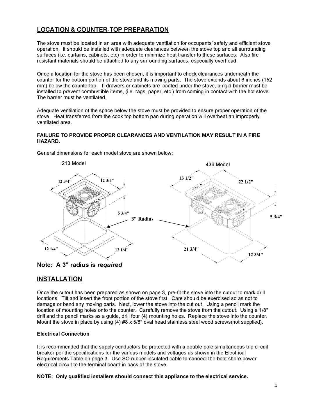
213, 436 specifications
Kenyon 213,436 is an advanced research vehicle designed for the exploration of Mars' surface and atmosphere. Built by a team of innovative engineers and scientists, this rover embodies cutting-edge technologies and features that enhance its operational capabilities in one of the most challenging environments in our solar system.One of the main features of Kenyon 213,436 is its robust mobility system. Equipped with multi-terrain wheels and an advanced suspension system, the rover can navigate rocky landscapes, steep slopes, and sandy dunes with ease. This flexibility allows it to reach various scientifically significant locations, maximizing the scope of its exploratory missions.
The rover is powered by a solar energy system combined with highly efficient batteries. This hybrid power source enables Kenyon 213,436 to harness sunlight during the Martian day while storing energy for use during the long, cold nights, ensuring continuous operation regardless of environmental conditions.
Kenyon 213,436 is outfitted with an array of scientific instruments designed for in-situ analysis of Martian soil and rock samples. Its onboard laboratory includes spectrometers, chemical analyzers, and a drilling mechanism. These tools enable the rover to collect and process samples, providing valuable data about Mars’ geology and potential for past life.
In terms of communication, Kenyon 213,436 features a high-gain antenna capable of transmitting data back to Earth with remarkable clarity. This communication system allows for real-time data exchange, enabling scientists to monitor the rover's findings and adjust its mission parameters dynamically.
The rover is also endowed with artificial intelligence capabilities, allowing it to operate autonomously. This AI system enables Kenyon 213,436 to make real-time decisions based on environmental conditions and mission objectives, enhancing its effectiveness in the field. It can also identify points of interest and prioritize tasks, reducing reliance on ground control and optimizing scientific returns.
In conclusion, Kenyon 213,436 stands as a pinnacle of modern engineering and planetary science. Its advanced mobility, power systems, scientific instruments, communication technologies, and autonomous capabilities equip it to contribute significantly to our understanding of Mars. Through its missions, Kenyon 213,436 is not only expanding our knowledge of the Red Planet but also paving the way for future exploration endeavors.