KD-ADA4 specifications
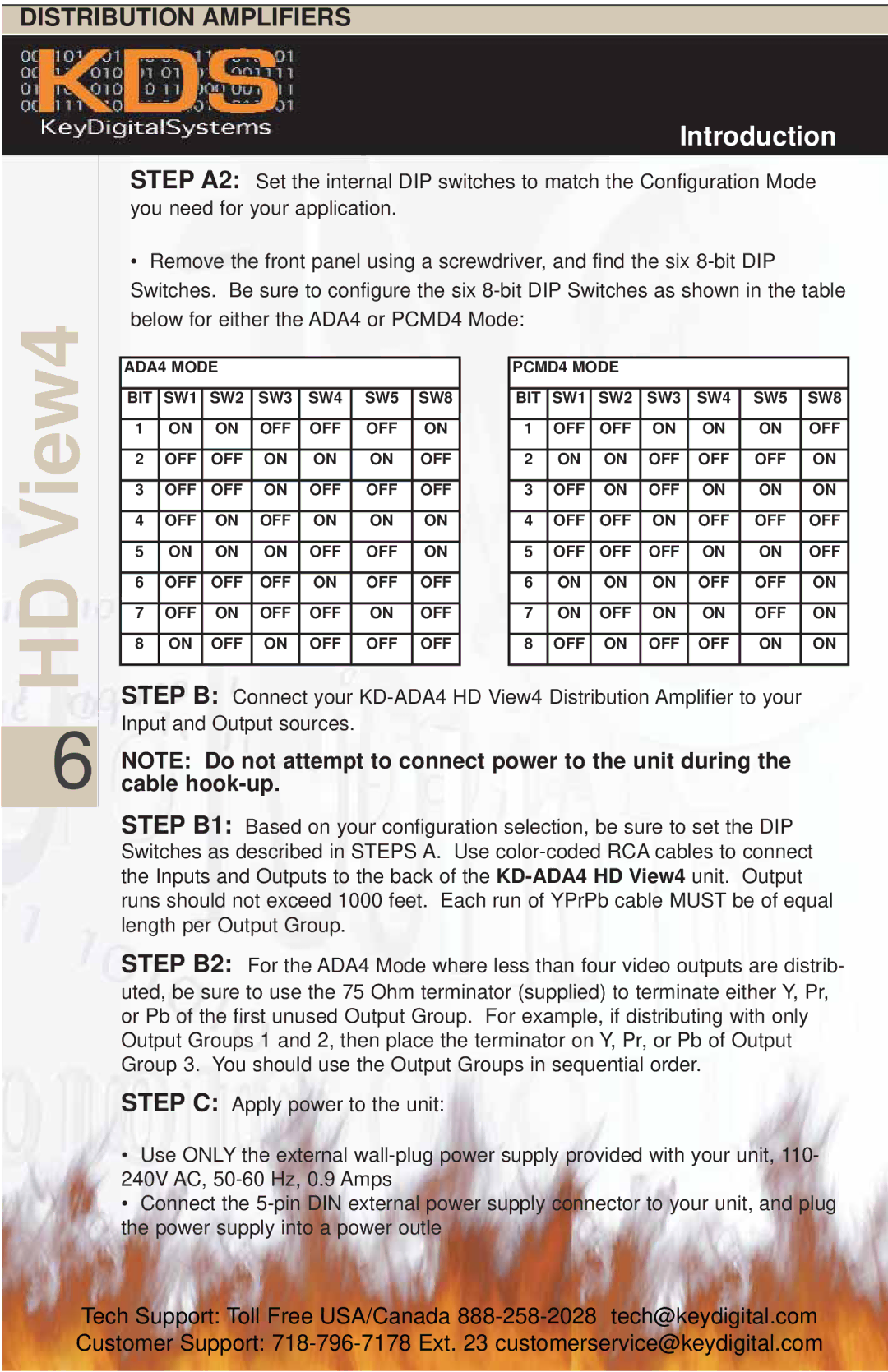
The Key Digital KD-ADA4 is an advanced audio distribution amplifier designed to offer high performance and flexibility for professional audio applications. As a versatile solution, the KD-ADA4 supports a variety of audio formats and delivers exceptional sound quality, making it ideal for integration in commercial spaces, educational institutions, and entertainment venues.One of the standout features of the KD-ADA4 is its ability to distribute audio to four separate outputs. This allows users to connect multiple audio zones or devices simultaneously, providing enhanced audio capabilities across a wide area. Each output can be independently controlled, giving users optimal control over their audio environment.
The KD-ADA4 utilizes state-of-the-art technologies, including digital signal processing (DSP), to provide dynamic range control, equalization, and other audio enhancements. The inclusion of DSP ensures that the audio remains clean and professional, regardless of the source material or environment. This is particularly beneficial in settings where audio clarity is paramount, such as in conference rooms or live event venues.
Another core characteristic of the KD-ADA4 is its compatibility with a variety of audio sources. It supports both analog and digital inputs, including balanced and unbalanced connections. This flexibility makes it easy to integrate the KD-ADA4 into existing audio systems, allowing users to leverage their current equipment while updating their audio distribution capabilities.
Furthermore, the KD-ADA4 is designed with user simplicity in mind. It features intuitive front panel controls and LED indicators that facilitate easy operation and monitoring of the system's status. For more advanced configurations, users can utilize Key Digital's proprietary software, which enables complex setups to be managed via a computer interface.
Robust build quality is another important aspect of the KD-ADA4. Designed to withstand the rigors of commercial use, it features durable hardware and an efficient cooling system to ensure reliable performance during extended operation. This makes it a dependable choice for projects where downtime must be minimized.
In summary, the Key Digital KD-ADA4 is a versatile audio distribution amplifier that combines advanced technology, comprehensive connectivity options, and user-friendly features. With its robust performance and flexibility, it is an essential tool for any professional audio installation requiring reliable audio distribution across multiple zones or devices.

