Assembly |
|
| |
| Figure 5 |
| |
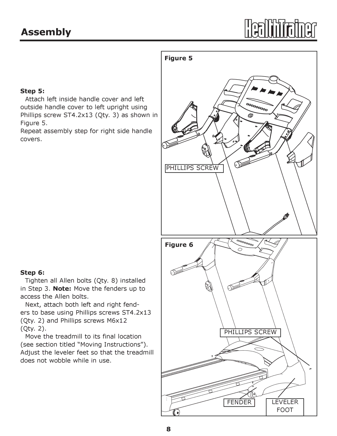
Step 5: |
|
| |
Attach left inside handle cover and left |
|
| |
outside handle cover to left upright using |
|
| |
Phillips screw ST4.2x13 (Qty. 3) as shown in |
|
| |
Figure 5. |
|
| |
Repeat assembly step for right side handle |
|
| |
covers. |
|
| |
| PHILLIPS SCREW |
| |
| Figure 6 |
| |
Step 6: |
|
| |
Tighten all Allen bolts (Qty. 8) installed |
|
| |
in Step 3. Note: Move the fenders up to |
|
| |
access the Allen bolts. |
|
| |
Next, attach both left and right fend- |
|
| |
ers to base using Phillips screws ST4.2x13 |
|
| |
(Qty. 2) and Phillips screws M6x12 |
|
| |
(Qty. 2). | PHILLIPS SCREW | ||
Move the treadmill to its final location | |||
|
| ||
(see section titled “Moving Instructions”). |
|
| |
Adjust the leveler feet so that the treadmill |
|
| |
does not wobble while in use. |
|
| |
| FENDER | LEVELER | |
|
| FOOT | |
| 8 |
| |
