3.2.4 PS/2 cable installation (with glidepad/microjoystick)
Installation must be carried out when the computer is switched off. If a keyboard and/or mouse is already connected to the computer, please remove it.
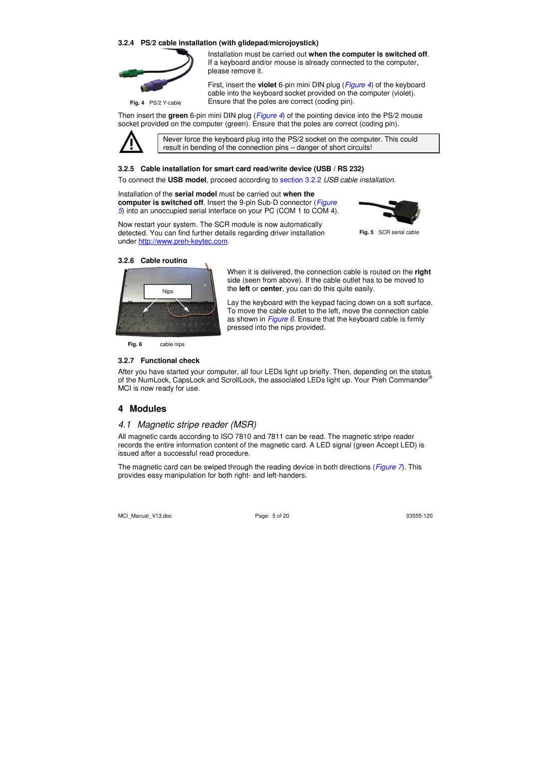
| First, insert the violet |
| cable into the keyboard socket provided on the computer (violet). |
Fig. 4 PS/2 | Ensure that the poles are correct (coding pin). |
Then insert the green
Never force the keyboard plug into the PS/2 socket on the computer. This could result in bending of the connection pins – danger of short circuits!
3.2.5 Cable installation for smart card read/write device (USB / RS 232)
To connect the USB model, proceed according to section 3.2.2 USB cable installation.
Installation of the serial model must be carried out when the computer is switched off. Insert the
Now restart your system. The SCR module is now automatically
detected. You can find further details regarding driver installation Fig. 5 SCR serial cable under
3.2.6 Cable routing
|
| When it is delivered, the connection cable is routed on the right |
|
| side (seen from above). If the cable outlet has to be moved to |
| Nips | the left or center, you can do this quite easily. |
|
| Lay the keyboard with the keypad facing down on a soft surface. |
|
| |
|
| To move the cable outlet to the left, move the connection cable |
|
| as shown in Figure 6. Ensure that the keyboard cable is firmly |
|
| pressed into the nips provided. |
Fig. 6 | cable nips |
|
3.2.7 Functional check
After you have started your computer, all four LEDs light up briefly. Then, depending on the status of the NumLock, CapsLock and ScrollLock, the associated LEDs light up. Your Preh Commander® MCI is now ready for use.
4 Modules
4.1 Magnetic stripe reader (MSR)
All magnetic cards according to ISO 7810 and 7811 can be read. The magnetic stripe reader records the entire information content of the magnetic card. A LED signal (green Accept LED) is issued after a successful read procedure.
The magnetic card can be swiped through the reading device in both directions (Figure 7). This provides easy manipulation for both right- and
MCI_Manual_V13.doc | Page: 5 of 20 |