
KS650.2, KS50.2, KS60.2 specifications
The Kicker KS650.2, KS50.2, and KS60.2 are part of Kicker’s renowned KS series of coaxial speakers, designed for car audio enthusiasts seeking a perfect blend of performance, clarity, and durability. Each model incorporates advanced design features and cutting-edge technologies, making them ideal for enhancing in-car sound systems and overall audio experiences.The Kicker KS650.2 represents a 6.5-inch coaxial speaker that delivers impressive sound quality and can handle high power levels effectively. With a peak power handling capacity of 300 watts per pair and a continuous power handling of 75 watts RMS, the KS650.2 ensures deep bass and clear mid-range frequencies. The polypropylene woofer cone offers an excellent balance of rigidity and lightweight properties, significantly improving transient response and overall sound reproduction.
Moving on to the KS50.2, this 5.25-inch coaxial speaker is perfect for smaller spaces without compromising audio quality. With up to 200 watts peak power and 50 watts RMS, it is designed for compact vehicles or smaller chambers within a larger audio setup. Its unique dome tweeter design delivers crisp highs, contributing to a balanced sound profile across all frequencies.
The KS60.2 emphasizes versatility with its larger 6x9-inch frame, making it a substantial upgrade for anyone looking to boost sound performance in their vehicle. This speaker provides powerful audio output with an impressive peak power handling of 300 watts and a continuous rating of 90 watts RMS. The innovative injection-molded polypropylene cone and oversized voice coil create remarkable clarity and efficiency, reducing distortion even at high volumes.
All KS series speakers feature advanced technologies such as a neodymium magnet for improved sensitivity and a customized grille that protects the driver while maintaining a sleek look. Combined with a frequency response range that extends from 40 Hz to 20 kHz, these speakers capture the full spectrum of music, ensuring that highs and lows are both clearly represented.
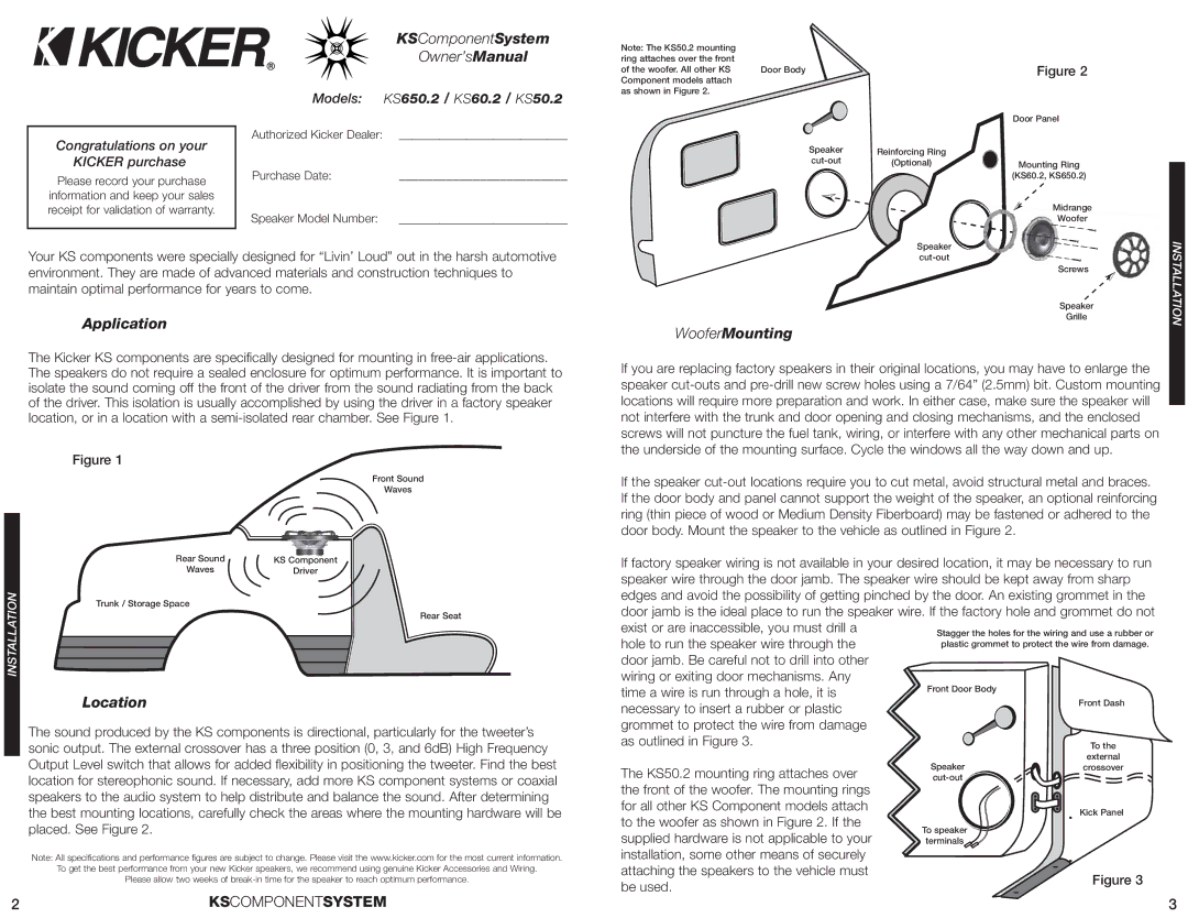
Installation is straightforward, as both KS650.2, KS50.2, and KS60.2 models come equipped with mounting hardware and user-friendly instructions. The Kicker KS series, with its blend of performance, durability, and aesthetics, provides car audio enthusiasts with speakers that not only sound amazing but also fit seamlessly into any vehicle’s interior design. Whether upgrading an existing system or building a new one from scratch, the Kicker KS650.2, KS50.2, and KS60.2 are exceptional choices to consider.