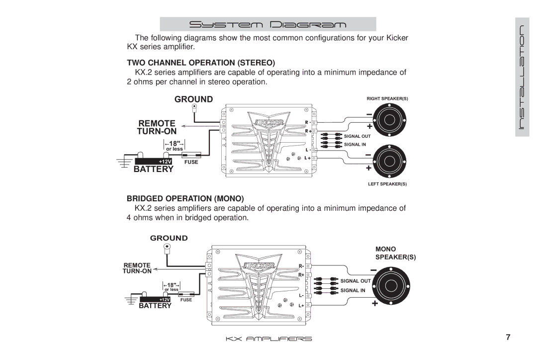
KX350.2 specifications
The Kicker KX350.2 is a high-performance compact amplifier renowned for its reliable power output and advanced features. Designed for those looking to elevate their car audio experience, this two-channel amplifier boasts a maximum power output of up to 350 watts, making it an excellent choice for driving various speaker configurations.One of the standout features of the KX350.2 is its Class D technology, which ensures that the amplifier remains efficient and cool even during prolonged use. This efficiency reduces power consumption while maximizing audio output, effectively delivering clear and powerful sound without draining the car's electrical system. The compact design also allows for easy installation in tight spaces, providing flexibility in mounting options.
The amplifier includes a variable low-pass crossover, adjustable from 50 Hz to 200 Hz, allowing users to tailor the audio output according to their preferences and the specifications of their speakers. The KX350.2 is also equipped with a selectable bass boost feature, providing an additional 6 dB of enhancement at 40 Hz to ensure that bass-heavy tracks sound rich and impactful.
For added convenience, the KX350.2 features speaker-level inputs, enabling a seamless connection to factory radio systems. This versatility ensures that car audio enthusiasts can upgrade their sound system without the need to replace the existing radio. Additionally, the amplifier comes with a 12-volt trigger input for easy on/off operation alongside the vehicle’s ignition, simplifying usage for everyday driving.
Durability is another key characteristic of the Kicker KX350.2. The amplifier is built with high-quality materials that resist wear and tear, making it suitable for various environments, including those exposed to moisture and temperature variations. The sleek design and robust construction give it a professional appearance that aligns with Kicker's reputation for quality.
With its combination of power, efficiency, and customizable features, the Kicker KX350.2 is an ideal amplifier for enthusiasts seeking to enhance their car’s audio system. Whether you are looking to drive high-performance speakers or want to bring out the best in your favorite tracks, the KX350.2 delivers impressive sound quality and reliability you can count on.

