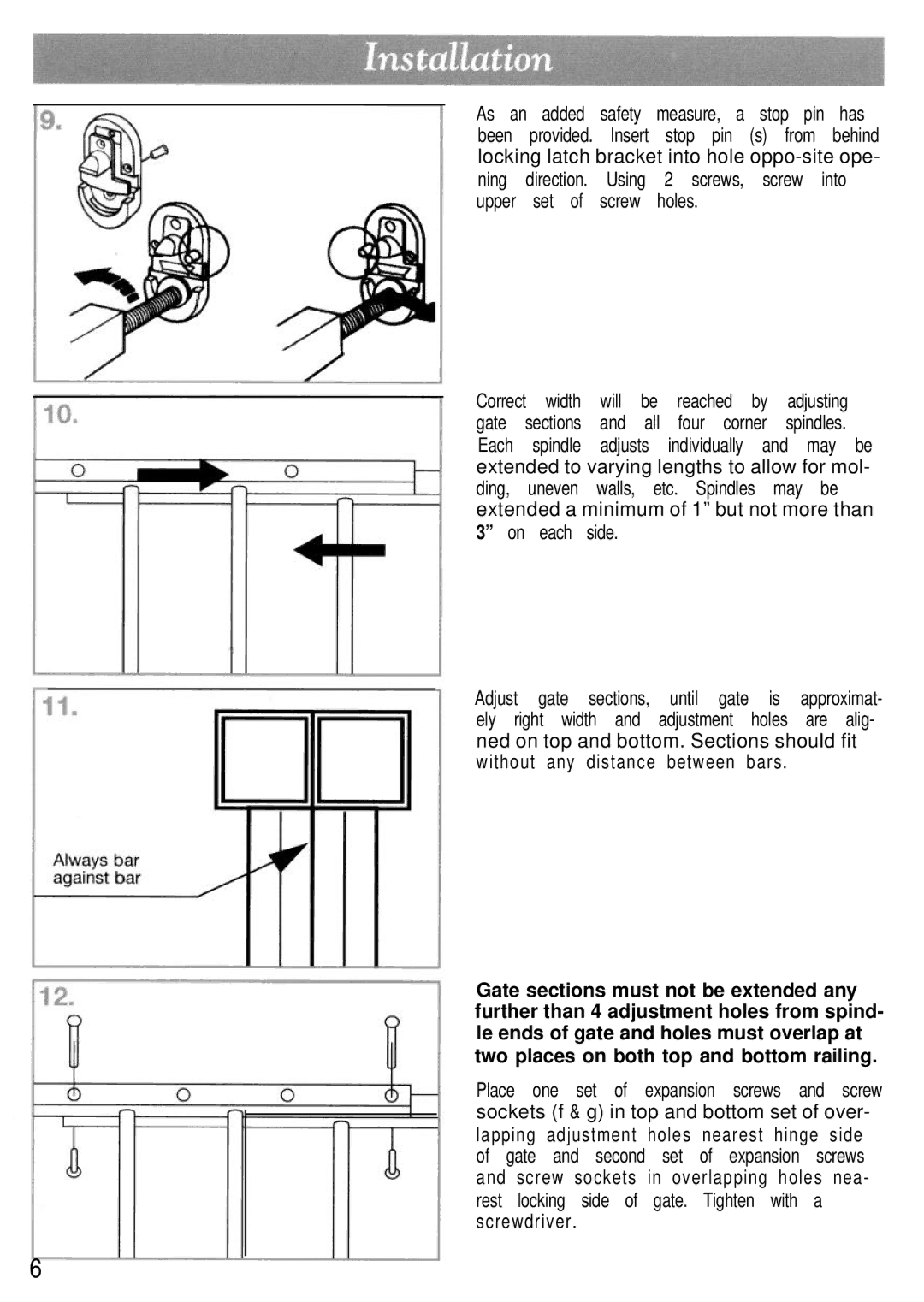
As an added safety measure, a stop pin has been provided. Insert stop pin (s) from behind locking latch bracket into hole
Correct width | will | be | reached | by | adjusting | |
gate | sections | and | all | four corner | spindles. | |
Each | spindle | adjusts | individually | and may be | ||
extended to varying lengths to allow for mol- ding, uneven walls, etc. Spindles may be extended a minimum of 1” but not more than 3” on each side.
Adjust gate | sections, | until gate is approximat- | |
ely right | width and | adjustment holes are alig- | |
ned on top and bottom. Sections should fit | |||
without | any | distance | between bars . |
Gate sections must not be extended any further than 4 adjustment holes from spind- le ends of gate and holes must overlap at two places on both top and bottom railing.
Place one set of expansion screws and screw sockets (f & g) in top and bottom set of over- lapping adjustment holes nearest hinge side of gate and second set of expansion screws and screw sockets in overlapping holes nea- rest locking side of gate. Tighten with a screwdriver .
6