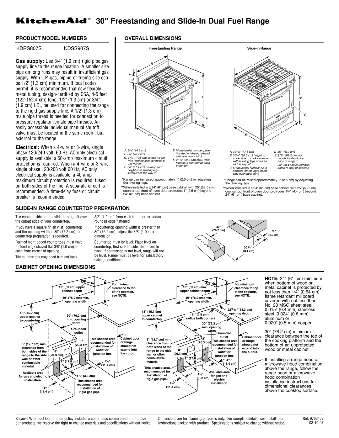
30" Freestanding and Slide-In Dual Fuel Range®

PRODUCT MODEL NUMBERS OVERALL DIMENSIONS

CABINET OPENING DIMENSIONS

SLIDE-IN RANGE COUNTERTOPPREPARATION

KDRS807S KDSS907S

Because Whirlpool Corporation policy includes a continuous commitment to improve
our products, we reserve the right to change materials and specifications without notice.
Dimensions are for planning purposes only. For complete details, see Installation
Instructions packed with product. Specifications subject to change without notice.
The cooktop sides of the slide-in range fit over
the cutout edge of your countertop.
If you have a square finish (flat) countertop
and the opening width is 30" (76.2 cm), no
countertop preparation is required.
Formed front-edged countertops must have
molded edge shaved flat 3/8" (1.0 cm) from
each front corner of opening.
Tile countertops may need trim cut back
3/8" (1.0 cm) from each front corner and/or
rounded edge flattened.
If countertop opening width is greater than
30" (76.2 cm), adjust the 3/8" (1.0 cm)
dimension.
Countertop must be level. Place level on
countertop, first side to side; then front to
back. If countertop is not level, range will not
be level. Range must be level for satisfactory
baking conditions.

Gas supply:Use 3/4" (1.9 cm) rigid pipe gas

supply line to the range location. A smaller size

pipe on long runs may result in insufficient gas

supply. With L.P. gas, piping or tubing size can

be 1/2" (1.3 cm) minimum. If local codes

permit, it is recommended that new flexible

metal tubing, design-certified by CSA, 4-5 feet

(122-152.4 cm) long, 1/2" (1.3 cm) or 3/4"

(1.9 cm) I.D., be used for connecting the range

to the rigid gas supply line. A 1/2" (1.3 cm)

male pipe thread is needed for connection to

pressure regulator female pipe threads. An

easily accessible individual manual shutoff

valve must be located in the same room, but

external to the range.

Electrical:When a 4-wire or 3-wire, single

phase 120/240 volt, 60 Hz, AC only electrical

supply is available, a 50-amp maximum circuit

protection is required. When a 4-wire or 3-wire

single phase 120/208 volt 60 Hz, AC only

electrical supply is available, a 40-amp

maximum circuit protection is required, fused

on both sides of the line. A separate circuit is

recommended. A time-delay fuse or circuit

breaker is recommended.

Ref. 9763462
03-19-07
18" (45.7 cm)
upper cabinet
to countertop
18" (45.7 cm)
upper cabinet
to countertop
13" (33 cm) upper
cabinet depth
13" (33 cm) max.
upper cabinet depth
30" (76.2 cm) min.
opening width
30" (76.2 cm) min.
opening width
For minimum
clearance to top
of the cooktop,
see NOTE.
For minimum
clearance to top
of the cooktop,
see NOTE.
30" (76.2 cm)
min. opening
width
30" (76.2 cm)
min. opening
width
This shaded area
recommended for
installation of
rigid gas pipe.
This shaded area
recommended for
installation of
rigid gas pipe.
This shaded area
recommended for
installation of
outlet or
junction box.
This shaded area
recommended for
installation of
outlet or
junction box.
Available area
for gas and electric
installation.
Available area
for gas and
electric
installation.
8"
(20.3 cm)
8"
(20.3 cm)
8"
(20.3 cm)
8"
(20.3 cm)
Grounded
outlet Grounded
outlet
7" (17.8 cm)
7" (17.8 cm)
1¹⁄2" (3.8 cm) 1¹⁄2"
(3.8 cm)
4¹⁄2"
(11.4 cm)
4¹⁄2"
(11.4 cm)
4¹⁄2"
(11.4 cm)
4¹⁄2"
(11.4 cm)
5" (12.7 cm) min.
clearance from
both sides of the
range to the side
wall or other
combustible
material.
Cabinet door
or hinge
should not
extend into
the cutout.
Cabinet door
or hinge
should not
extend into
the cutout.
5" (12.7 cm) min.
clearance from
both sides of the
range to the side
wall or other
combustible
material.
¾" (1.9 cm)
radius both corners
22
¹⁵⁄₁₆
" (58.3 cm)
opening depth
F
reestan
di
ng
R
ange*Range can be raised approximately 1" (2.5 cm) by adjusting the leveling legs.**When installed in a 24" (61 cm) base cabinet with 25" (63.5 cm) countertop; front of oven door protrudes 1" (2.5 cm) beyond 24" (61 cm) base cabinet.
Slid
e-
i
n
R
ange*Range can be raised approximately 1" (2.5 cm) by adjusting the leveling legs.**When installed in a 24" (61 cm) base cabinet with 25" (63.5 cm) countertop; front of oven door protrudes 1³⁄₄" (4.4 cm) beyond 24" (61 cm) base cabinet.
A.5³⁄₄" (14.6 cm)
B.30" (76.2 cm)
C.41³⁄₄" (106 cm) overall height
with leveling legs screwed all
the way in.
D.36" (91.4 cm) cooktop trim
height with leveling legs
screwed all the way in*
E.Model/serial number plate
(located on the right-hand
side oven door trim)
F.2 7
¹⁄₄
" (69.2 cm) max. from
handle to standoff at back
of range**
AB
E
D*CF**
A.30⁹⁄₁₆" (77.6 cm)
B.35⁵⁄₈" (90.5 cm) height to
underside of cooktop edge
with leveling legs screwed
all the way in*
C.Model/serial number plate
(located on the right-hand
side oven door trim)
D30" (76.2 cm)
E.27¼" (69.2 cm) from
handle to standoff at
back of range**
F.2 3 " ( 58 .4 c m) countertop
notch to rear of cooktop
B*DAE**
C
F
30"
(76.2 cm)
30 ³⁄₄"
(78.1 cm)
³⁄₈"
(1.0 cm)

NOTE:24" (61 cm) minimum

when bottom of wood or

metal cabinet is protected by

not less than 1/4" (0.64 cm)

flame retardant millboard

covered with not less than

No. 28 MSG sheet steel,

0.015" (0.4 mm) stainless

steel, 0.024" (0.6 mm)

aluminum or

0.020" (0.5 mm) copper.

30" (76.2 cm) minimum

clearance between the top of

the cooking platform and the

bottom of an unprotected

wood or metal cabinet.

If installing a range hood or

microwave hood combination

above the range, follow the

range hood or microwave

hood combination

installation instructions for

dimensional clearances

above the cooktop surface.