Cat wires from rooms with more than one VC201 are run from one VC201 to the other then home run back to the controller.
It is very important to use a top quality RJ45 8/8 crimper tool. We strongly suggest using a cat 5 RJ45 electronic tester to verify the wire conductors.
Connection to Stereo Equipment: Remove the VC224pm orVC226pm green
VC224pm and VC226pm controllers are rated for use with maximum 120 watt per channel amplifiers. DO NOT use
The amplifier or receiver must be rated for four ohm speaker use to work properly with the VC224pm or VC226pm controller. Connect the controller to the amp or receivers speaker A or speaker B terminals. Wire the VC224pm or VC226pm connectors labelled “ROOM1", "ROOM2" etc. directly to the correct room speakers, again strictly observing polarity.
Power Requirements: The VC224pm and VC226pm are shipped with a 12VDC 500mA (or more) power supply (supplies power to the keypads). If possible, connect the 12vdc power supply to the switched outlet on the rear of the amplifier or receiver. This wiring causes the VC224pm or VC226pm controller to reset to its selectable “boot up” every time the receiver or amplifier is turned on but when the power is off the IR section of the VC201i will not work. If the IR is required to work all the time, then the controller power supply must connected to an unswitched outlet.
Installer Selectable “BOOT UP”: The VC224pm and VC226pm allow the installer to select how the volume control “boots up” in each room when the controller first receives 12vdc power. For this feature to work, be sure to plug the 12vdc power supply to the switched AC outlet on the rear of the receiver or amplifier. Please note #6/12 and S/Mute labels are inverted on zones 2, 4 and 6 on the version 1.3 board.
To always Start MUTEed make sure the shunt on the right side of the controller room number labelled “S/MUTE” is in place. Remove this shunt and this room starts with the music on.
To always start up in a quiet position #6 (of 17) sure the shunt on the right side of the controller room number labelled “# 6/12” is in place. Remove this shunt if this room is to start in the louder position #12.
To restore the boot up defaults, replace the appropriate room shunts.
Installation
Installing the digital volume control system should be relatively easy. With a bit of planning, it will give trouble free service for years.
Basic System Layout and
One or two VC201 keypads can work on a single room or zone but only one VC201i can be connected to a single VC224pm or VC226pm room or zone. The VC200 keypad does not work with this system.
Use the standard T568A wiring practices to run a cat 5 or cat 3 wire from the keypad or controller to the VC224pm or Vc226pm. If more than one keypad controls a single VC224pm or Vc226pm room, daisy chain the cat wire from keypad to keypad. If the VC226pmi is not located next to the stereo, run a single
From each speaker run a home run fire rated
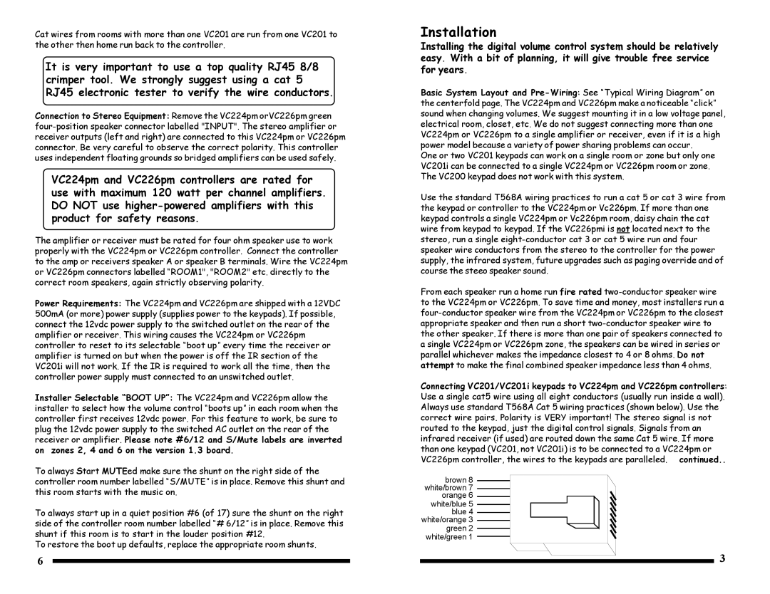
Connecting VC201/VC201i keypads to VC224pm and VC226pm controllers: Use a single cat5 wire using all eight conductors (usually run inside a wall). Always use standard T568A Cat 5 wiring practices (shown below). Use the correct wire pairs. Polarity is VERY important! The stereo signal is not routed to the keypad, just the digital control signals. Signals from an infrared receiver (if used) are routed down the same Cat 5 wire. If more than one keypad (VC201, not VC201i) is to be connected to a VC224pm or VC226pm controller, the wires to the keypads are paralleled. continued..
brown 8 white/brown 7 orange 6 white/blue 5 blue 4 white/orange 3 green 2 white/green 1
6 | 3 |