VC224pm and VC226pm typical wiring diagram
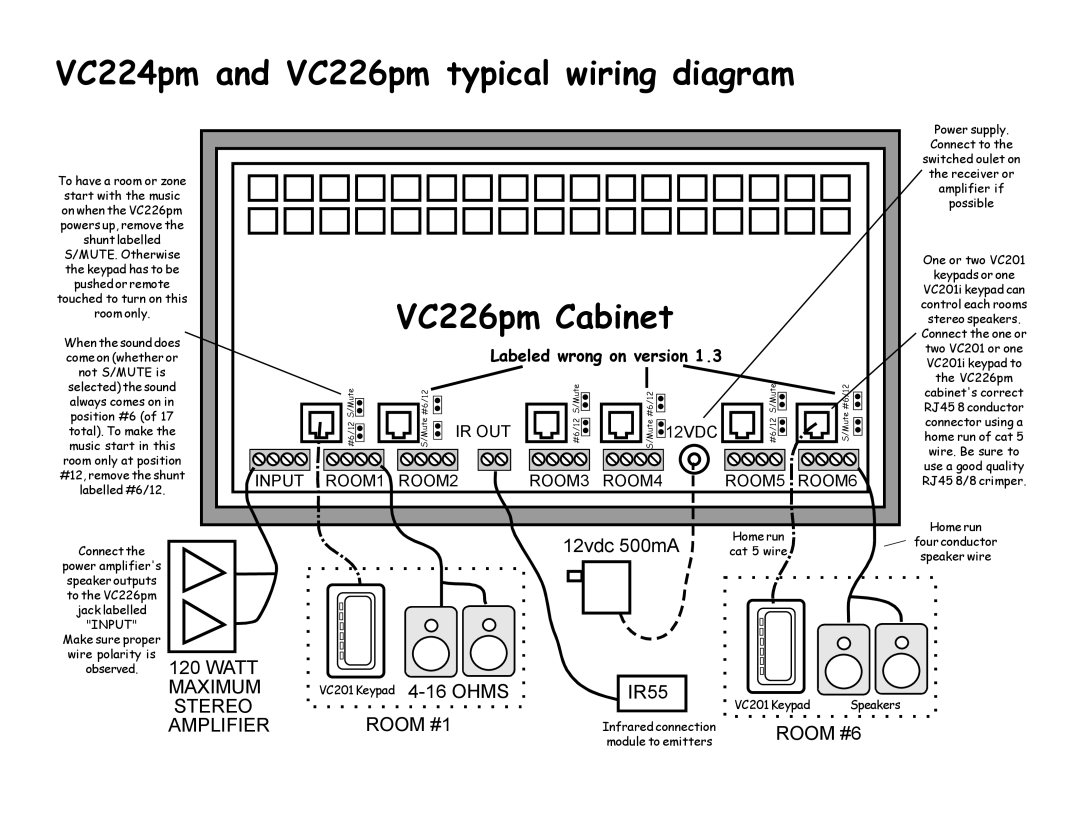
To have a room or zone start with the music on when the VC226pm powers up, remove the shunt labelled S/MUTE. Otherwise the keypad has to be pushed or remote touched to turn on this room only.
When the sound does come on (whether or not S/MUTE is
VC226pm Cabinet
Labeled wrong on version 1.3
Power supply. Connect to the switched oulet on the receiver or amplifier if possible
One or two VC201
keypads or one
VC201i keypad can control each rooms stereo speakers. Connect the one or two VC201 or one VC201i keypad to
the VC226pm
selected) the sound always comes on in position #6 (of 17 total). To make the music start in this room only at position #12, remove the shunt
labelled #6/12.
#6/12S/Mute | S/Mute#6/12 |
| IR OUT |
![]() INPUT
INPUT ![]() ROOM1 ROOM2
ROOM1 ROOM2
#6/12S/Mute | S/Mute#6/12 | #6/12S/Mute | S/Mute#6/12 |
|
| 12VDC |
|
ROOM3 ROOM4 | ROOM5 ROOM6 | ||
cabinet's correct RJ45 8 conductor connector using a home run of cat 5 wire. Be sure to use a good quality RJ45 8/8 crimper.
Connect the
power amplifier's speaker outputs to the VC226pm jack labelled "INPUT"
| Home run | Home run | |
12vdc 500mA | four conductor | ||
cat 5 wire | |||
speaker wire | |||
|
|
Make sure proper
wire polarity is
observed.
120 WATT |
|
MAXIMUM | VC201 Keypad |
STEREO | ROOM #1 |
AMPLIFIER |
IR55 |
Infrared connection module to emitters
VC201 Keypad Speakers
ROOM #6