|
|
|
|
| Your | ||||||||||
|
|
|
| Table 1: | |||||||||||
|
|
|
|
|
|
|
|
|
|
|
|
|
|
|
|
| # | Feature |
|
| Function |
| |||||||||
| 1 | 12V DC |
|
| +12V DC connector for powering the unit |
| |||||||||
| 2 | CAT 5 |
| Connect to1 the CAT 5 |
| ||||||||||
| 3 | PC / DEVICE Button |
| Press when a device is connected to the |
| ||||||||||
|
|
|
|
|
| Release when a PC is connected to the |
| ||||||||
| 4 |
|
| Connects to either a PC or a device |
| ||||||||||
|
| Connector |
|
| PINs 2, 3 and 5 are passed through the device |
| |||||||||
| 5 | GREEN=PC |
| LED |
| Lights in green when the PC/DEVICE button is released and in red |
| ||||||||
|
| RED=DEVICE |
|
| when the PC/DEVICE button is pressed |
| |||||||||
|
|
|
|
|
| ||||||||||
|
|
|
|
|
|
|
|
|
|
|
|
|
|
| |
|
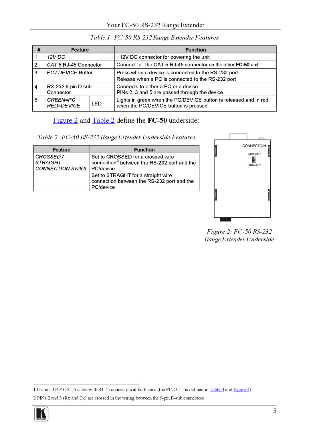
| Figure 2 and Table 2 define the | |||||||||||||
| Table 2: |
|
|
|
| ||||||||||
|
| ||||||||||||||
|
|
|
|
|
|
| |||||||||
|
|
|
|
|
|
|
|
|
|
|
|
|
|
|
|
|
| Feature |
|
|
| Function |
|
|
|
|
|
|
|
| |
|
|
|
|
|
|
|
|
|
|
|
|
|
| ||
| CROSSED / | Set to CROSSED for a crossed wire |
|
|
|
|
|
|
| ||||||
|
|
|
|
|
|
|
|
| |||||||
|
|
|
|
|
|
|
| ||||||||
| STRAIGHT | connection2 between the | |||||||||||||
| CONNECTION Switch | PC/device | |||||||||||||
Set to STRAGHT for a straight wire connection between the
Figure 2: FC-50 RS-232
Range Extender Underside
1 Using a UTP CAT 5 cable with
5