Your
4Your PT-1Hs Hs Delay Corrector
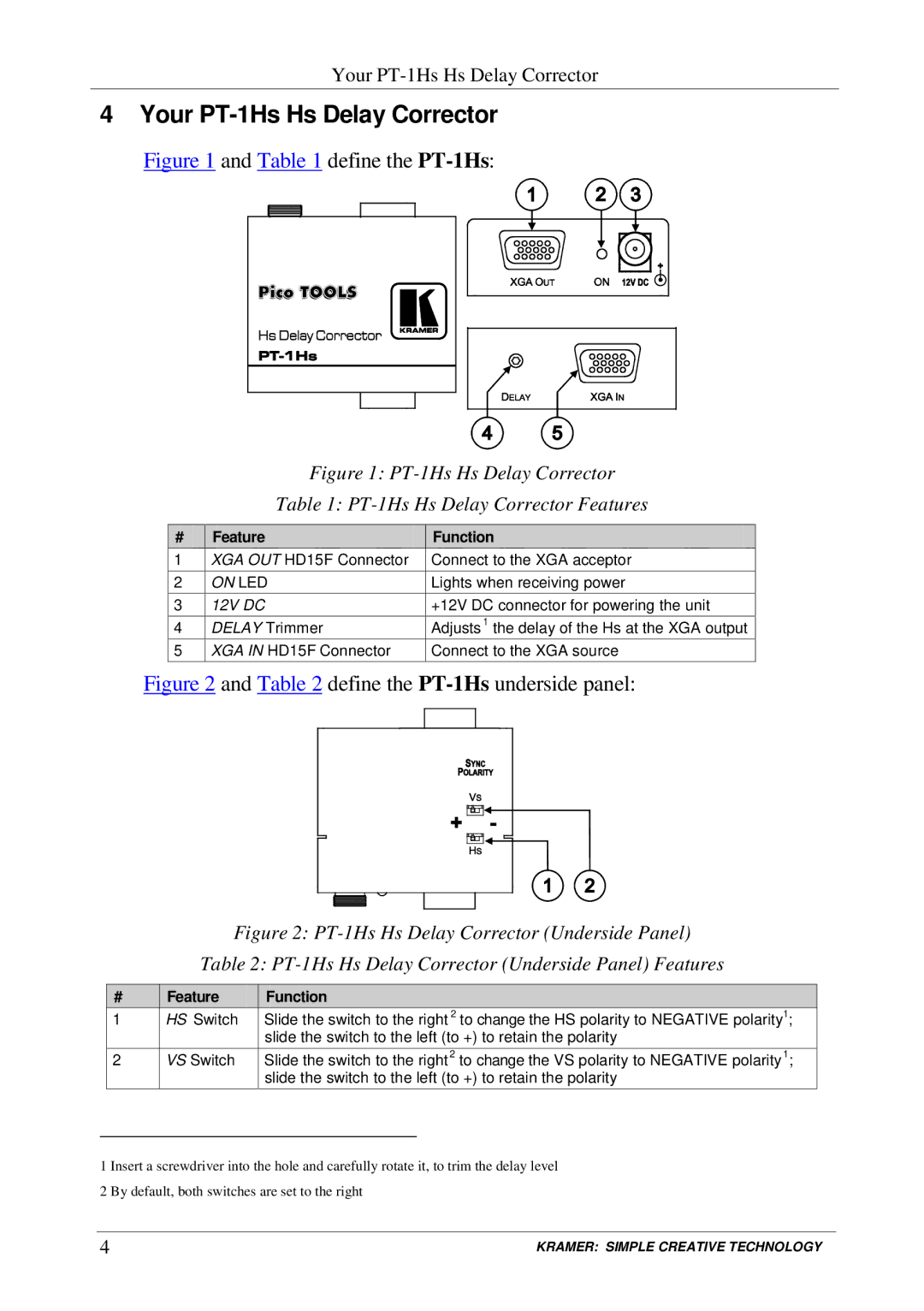
Figure 1 and Table 1 define the PT-1Hs:
Figure 1: PT-1Hs Hs Delay Corrector
Table 1: PT-1Hs Hs Delay Corrector Features
# | Feature | Function |
1 | XGA OUT HD15F Connector | Connect to the XGA acceptor |
2 | ON LED | Lights when receiving power |
3 | 12V DC | +12V DC connector for powering the unit |
4 | DELAY Trimmer | Adjusts1 the delay of the Hs at the XGA output |
5 | XGA IN HD15F Connector | Connect to the XGA source |
Figure 2 and Table 2 define the PT-1Hs underside panel:
Figure 2: PT-1Hs Hs Delay Corrector (Underside Panel)
Table 2: PT-1Hs Hs Delay Corrector (Underside Panel) Features
# | Feature | Function |
1 | HS Switch | Slide the switch to the right 2 to change the HS polarity to NEGATIVE polarity1; |
|
| slide the switch to the left (to +) to retain the polarity |
2 | VS Switch | Slide the switch to the right2 to change the VS polarity to NEGATIVE polarity1; |
|
| slide the switch to the left (to +) to retain the polarity |
1 Insert a screwdriver into the hole and carefully rotate it, to trim the delay level 2 By default, both switches are set to the right
4 | KRAMER: SIMPLE CREATIVE TECHNOLOGY |